WELCOME BACK !!!!
Now that we have learned how the clock functions (and have looked at 5.325 million designs) let's see what we decided on.
We used the 4510 chip in our final design for the 12 hour clock. It was the easiest route to take. But it was fun learning how to make a clock go from 12 to 1 using standard timer chips. It was much more complicated but it did work as designed.
We were going to piggyback the 1 HZ module on the main board but decided against it. So we will build it directly onto the clock board. I will be using the 4060/4013 version.
We are also going to use the SAME 1 HZ counter to supply the SAME count to the 24 hour clock as well. More on that later.
A word here about the 1 HZ circuit. I built a ton of them on the breadboard, and they ALL worked. (Some more accurate than others) But when I put them on a circuit board, they gave me FITS. It turned out that because of my poor soldering techniques, we were burning up the CRYSTALS.... So, I beg you-------- Heat sink the crystal when soldering. I have a little tool I use.
 So here we go .......


1 HZ Generator - 4060 with 4013 version
Here is our final design for the 12-hour version. The pull-down resistors may not be needed but I added them to help stabilize the AND gates.


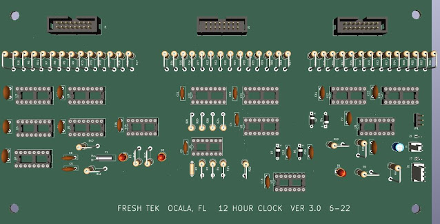
And the Circuit Board
 Now let's build this on the bread board.
 Wanna see it go from 12 o'clock to 1 o'clock?
Course you do.
Now that we have the design and it seems to work on the Bread Board, let's build the Prototype. We built the Display Board earlier in our journey, so we will move directly to the main board. For the main board, I will be using one of the boards we bought from Amazon.

(I cut it in HALF to get the board for the other clock.)
Using my schematic we start by placing our IC Sockets, Jacks, resistors, caps, and diodes.
Then we run our Power and Ground Bus, and wire power and ground to the IC's.


HELPFUL HINT - I label all the sockets with the name of the IC. It will help when I start doing the point to point wiring,

Ready to run the POWER AND GROUND BUSES
 Starting to run the buses
As far as the point-to-point wiring goes, start with the 4511 outputs to the resistors then onto the jack that runs to the display board. (Don't forget to TEST as you go along.)
Here is the proto type with all the 4511's wired to the resistors then to the output jacks that feeds the Display Board. After testing I use some finger nail polish to secure the small wires so they don't move and break a connection. If you don't like the 'look', you can use CLEAR polish.
Let's wire up the outputs from the 4518's to the 4511's.
Another way to secure your wires is with a piece of copper wire. I cut a 3 inch piece and make a "U". Then I insert it across the wire through two holes. I then turn the board over and twist the two ends together. I don't really care for this look, but I do use this method to hold wires tight against the board while the 'polish' dries. I then cut the copper wires and remove them, thus leaving the secured wire in place.
BUT, don't make it too tight !!!!!!-------------------------------------------------------------- Now let's wire up the 4510's.
Once we complete that task, we can move on to the inputs to the 4510's and the 4518's.
Start with the seconds module..
Once the SECONDS Module is complete and working, move on to the minutes section. (Do not hook the seconds output to the minutes input YET)
Now you can build out the MINUTES section of your clock.
Get it working before moving on.
Now that the SECONDS and MINUTES are working and counting, you can now run the leads from the SECONDS module to the MINUTES module. Does the Second output count the Minutes??? Yes, it does.
Move onto the HOURS Module, and get it up and running. Once done with the hours, you can connect it's input to the pulse coming out of the minutes module.
Now add the set switch panel. (The next chapter will have more info on the Switch Controller design.)
The clock controller we designed using the two HERTZ pulse to set the hours and minutes, never worked as planned. (it required several OR gates and got a bit complicated.) So we decided to use 5 volts thru a tactile switch. With a resistor and capacitor, it worked PERFECTLY. I finally realized that I was making this clock more DIFFICULT than it needed to be.
Here is the FINAL design for the switch panel. I wanted to use tactile switches. They seemed to work better than the toggles that I tried.
Could not be simpler.
To set the clock, simply hit 'RESET' when your master clock seconds hit "00".... Then set the minutes, by pushing the 'SET MIN' switch enough times to advance to the current minute,
Do the 'Hours' the same way.
Congratulations, You just built a digital clock.
The 24 hour version is made in the same manner. The biggest difference is the omission of the 2 x 4510 chips. They are replaced by ONE 4518 chip.
Here is your schematic for the 24 hour version.
AND THE BOARD TO GO WITH IT


Just follow the schematic and build it using the techniques described above.
Now let's talk about some of the custom modifications that I made since I'm running 2 clocks and one timer.
I used the same 1 HZ counter for BOTH clocks, in order to keep the 'seconds' count the same. I used jumpers so if one of the modules dies, I can still keep both clocks running. Since I built 1 HZ counters on both boards, I can use the unused counter to flash the LEDS between the segments. Or I can add another AND gate. That's what I decided upon.
Now that the clocks are done I am thinking about the timer. I don't think I'll be counting past 60 minutes, but what the hell. Let's build a six digit timer. You can easily leave off the hours section if you so desire.
BUT, let's not get ahead of ourselves.
Let's move onto the discussion about the controller, then we can build a cabinet for the clocks.
YOU CAN NOW PROCEED TO CHAPTER 8 - - - CONTROLLING THE CLOCK.
God Speed, Mother Nature.

