
And welcome back, We can now take a look at how to set and re-set the 6-digit clock.
Over the course of the last few months, I have been building (and modifying) a control panel.
I determined that it was BEST to have a controller for the CLOCK, and a different controller for the timer.
Here is the first version (CLOCK) that I tried. 
Here is a look at the control switches. Used for setting the minutes and hours. We can also reset all the digits to ZERO as well as putting the 'count' in a HOLD mode.
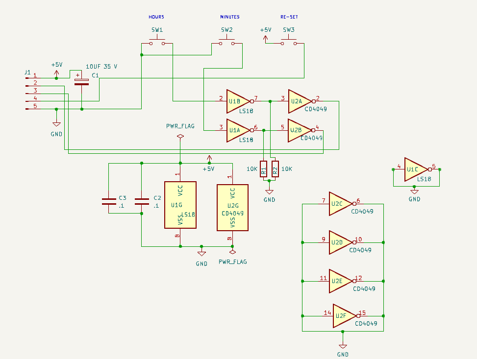
Let's look at the big picture.

The re-set is the easiest. The re-set switch sends 5 V to each reset pin. This pulse goes through 6 1n4148 signal diodes to protect each pin from any stray pulses.
Let's see how the minutes can be set. (The hours work the same way.)
A pulse from the 10's of seconds digit, sends a HIGH to an OR gate. Whenever the OR Gate sees a HIGH on either PIN it will send a HIGH to the counter.
We are feeding a 2 hz. signal into the minutes set switch. When that switch is closed, the 2 HZ pulse is set to the other input of the OR gate. It will send a 2 HZ HIGH to the count pin. Simply open the switch when you get to the count you want.
Using momentary switches are a help in this application.
If you want to STOP the Clock, (HOLD the Count) simply close the HOLD Count switch.
When the HOLD Count switch is open the 1 HZ timing pulse routes through the switch and onto the Seconds counter.
When closed the 1 HZ count pulse is replace by 5 V. Thus stopping the seconds digit from counting.
Open the switch and the 5 V is replaced by the 2 HZ pulse, and counting continues.
-----------------------------------------------------------------------------------
There are a couple of issues with the above.
First, it adds yet MORE I.C.'s to the project and second, why do we need a "re-set"? This is a clock not a timer. And it requires sending the seconds pulse through the switch panel. Let's try to make it SIMPLE.


+5 volts enters the set switch (S-2) on the left.
When closed, the 5 volts goes to a 1n4148 diode then onto the enable pin of either the minutes or hours. A capacitor to ground helps to "de-bounce" the switch.

And it works!!!!! The pull-down resistors are not critical, but they do provide some stability to the AND gates.
If you want to add more chips, you could use the 2 HZ pulse to set your clock. However, I found that to be overkill.
We did add a HOLD switch, just like on the clock kit that we built.
It simply sends 5 Volts to the 1 HZ IN pin. That will override the 1 HZ pulses and put the clock in the "HOLD" position.
To set your clock, simply put it in the HOLD position when your master clock hits :00.
Then set your minutes to the next minute, and the hours to the correct hour.
When your master clock hits that time, simple turn the HOLD to RUN.
Done.
BUT WAIT!!!!!!! This did not work as planned. Sometimes the clock would 'jump' when you set it to run. Debouncing the switch did not solve the issue, but it did help.
SO, let's think a bit.
Why 'pause' the clock waiting for the for the master clock (seconds" to catch up????
Let's just RESET the seconds to :00, then set the minutes and the hour???
In order to reset the seconds, we need to remove the GND from PIN 7 of the 4518. I added a 10 K ohm pull down resistor to PIN 7 and GND.
Now I can re-set the clock seconds to :00 when the master clock reaches :00.
It worked like a charm.
Here is the final design:

As my old friend Lee Corso likes to say,

I still had an issue with some switches not working as desired. So, I kept looking.

You can score these from DIGI-KEY.


.


No comments:
Post a Comment