
Welcome back.
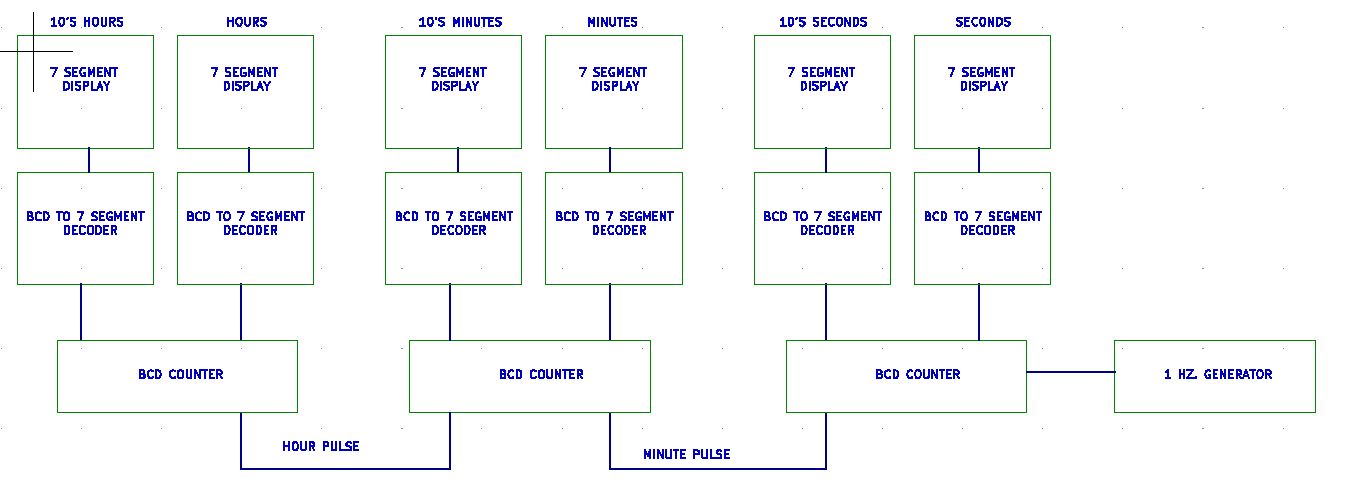
To understand how this magic all happens, let's take a look at a Block Diagram of a digital Clock.


If you look at the third line, you will see the 0 0 0 0 signifying the digit 0.

0 1 1 0
Yep, when the tens digit hits "6" we will see a 'High' on BCD lines "c" and "b".
In our chip that is pins 4 & 5. Using an 'and' gate we can insert those two "highs" and get a pulse at :60 to reset the Counter. (AND feed a pulse to the next section.
But doesn't line 'c' and 'b' also go high on the number 7??
Very true my friend, But the tens digit will never reach 7 since it will reset when it reaches 6. Brilliant, isn't it??
A quick word about AND gates.
One of the easiest multiple-input gates to understand is the AND gate, so-called because the output of this gate will be “high” (1) if and only if all inputs (first input and the second input and . . .) are “high” (1). If any input(s) is “low” (0), the output is guaranteed to be in a “low” state as well.
The most common AND gates are the 2 input and 3 input. There are AND gates made with more than three inputs, but this is less common than the simple two-input variety.
A two-input AND gate’s truth table looks like this:

So if you place a 'LOW' on any of the two inputs, you will see a 'LOW" at the output. BUT, if you place a "HIGH" on each input you will see a 'HIGH' on the output.
Remember we said that the number 6 gives you a 'HIGH' on two pins, we feed those 'HIGH's' to the AND gate. We only get a 'HIGH on the output when the digit reaches # 6. We use that "HIGH' to reset the timer to '0' And the process repeats itself.
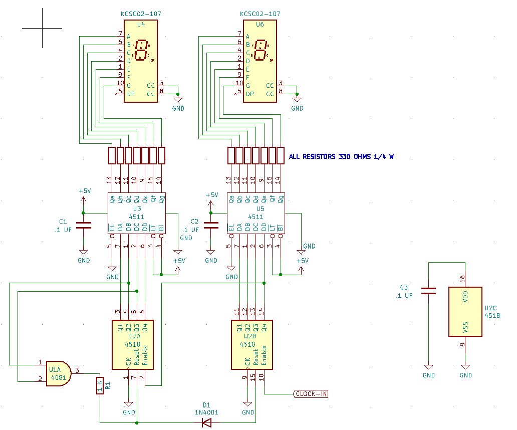
Let's go ahead and bread board this circuit and play with it.
When you get this up and running, you can build a duplicate circuit as well... This will be for the minutes.
Now comes the hour. This one is a bit 'trickier' than the Seconds and minute because we want it to go from 12 to 1 NOT 12 to 00.
I found many circuits online but they would only go from 12 to 0. That's fine for a 12-hour TIMER but not for a clock. Designing the 24-hour clock was easier.
Let's take a look at that schematic for the hours section.

Now comes the hard part. Getting a 12-hour clock to work.
(Spoiler Alert) I will tell you at the end how to accomplish this the EASY way. But I wanted you to understand the circuit.
Since I could not find a circuit that worked, I studied up on how these chips function. As we learned earlier, each number has its own unique code 0,0,0,0 for the number zero. 0,0,0,1 for the number 1.

Resetting our clock to :00 is easy, but we need to build on that and get that :00 to move to :01.
So, let's get a 12-hour circuit that resets to :00

In order to reset from '12' to '00' we need to see a '1' in the tens place and '2' in the sec place.
Looking at our chart, we see that when it displays a '1' pin 6 on the tens unit goes high.
SO WE HAVE A '1'
Now we see that when a '13' is displayed PINS 11 & 12 goes HIGH.
WE NOW HAVE OUR '2'.
Let's feed the 11 & 12 pins into an AND gate.
The output of that gate goes to an input on another gate.
The other input of that gate is connected to PIN 6 on the tens unit.
So when the unit displays a '3', we get a High on the output of the AND gate. Feeding that into another AND gate along with the HIGH from Pin 6, we get a HIGH on the output of the second AND gate. We can use that HIGH to reset BOTH counters to '00'.
So we reset the unit to '00', we can work with that.
We can feed each digit into to 4 input AND GATE.

In order to go from '0' to '1' we need to see ZERO on both displays. Feed each of the 4 lines into a NAND gate (U-6A and U-6B) and we get 2 high's out.
We then feed each of the HIGH's into another AND gate (U5D) to get a HIGH out.
Since we need a PULSE (rising and lowering) this HIGH will NOT work to count the hour digit.
BUT
If we take that HIGH and feed it to another AND gate (U-5B), we can just use the 1 or 2 HZ pulses to feed the other input of that AND gate. This will give us a PULSE that we can use.
That output will be sent to the count pin (Pin 10 of the 4518) We then go from 00 to 01.
But I don't want to see the zeroes.
You won't for very long because of the speed at which these chips work. The '00' shows up only long enough for the Gates to do their magic and increase the count. When that happens the '00' disappears. Using the One HZ counter on that AND Gate means the '00' may show up for ONE SECOND. If you use a TWO HZ pulse the '00' may show for as long a 1/2 sec.
But remember, this only happens 2 times a day for maybe a second or two. I think it's a fair trade off. Don't you? Course you do.
Now the SURPRISE: Check out this diagram.

In this case the clock pulse comes in to pin 15, (not 10). and, this chip is DIFFERENT. The 4510 does the same job as the 4518 EXCEPT you can get it to always go to the number '1'. (Thus, avoiding MORE IC's.)
I tried this one out, and it works!!!!!!!! So, we can use 2 of the 4510's in our hour circuit.

That's all the time we have for today. We now have a working schematic for a nice 24 or 12 hour clock.
But Hoss, how do we set the timer ????
We need a control panel. And we will get to that soon.
Next time we will finish up the proto types and discuss building the clock and getting it running.
See you then.
YOU CAN NOW MOVE ONTO CHAPTER 7 - - - BUILD THE CLOCK
God Speed, Mother Nature.


No comments:
Post a Comment