Sunday, April 10, 2022

CHAPTER 3 - - - THE POWER SUPPLIES

Let's talk about power supplies.  (I always try to start with the easy ones.)

-----------------------------------------------------------------------------------

NOTE: Make sure your read ALL the way to the end BEFORE you start building. Numerious design changes were made along the way. It was a fun journey, and a great learning experience,

-----------------------------------------------------------------------------------

The RS 6 & 12 series of consoles used an off the shelf +/- 15 volt supply from CONDOR.


The RS 18 & 24 added an additional 15 volt supply to handle the extra load.


All the consoles in the line used a Radio Systems +/- 7.5 VOLT SUPPLY


I found the +/- 15 VOLT supply on line, but the price was way above my pay grade.  

So let's pitch that idea and come up with something that will work, without breaking the bank. And that is why we are making our own. Plus you will learn how a Power Supply works.

Back in the day, I did build one of these and it ran perfect for over 2 years. The only "Off The Shelf" power supply was for the 5 volt cock/timer.


LEFT TO RIGHT -  POWER TRANSFORMER  +/- 15 VOLT SUPPLY

TOP LEFT -  BARRIER STRIP, FOR POWER IN AND OUTPUTS

TOP CENTER  -  FUSES / ON-OFF SWITCH AND 110 V INDICATOR

RIGHT SIDE TOP -   OFF THE SHELF 5 VOLT SUPPLY

RIGHT MIDDLE  - +/- 7.5 SUPPLY

BOTTOM - HEAT SINK


Here are some shots of that Power Supply under construction (I wish now I would have saved that P. Supply.)

No, the holes are not on the wrong side. The plexi glass front is turned over.
Yes, I did change the Power Transformer in the final version


-----------------------------------------------------------------------------------

Now that we have talked about what I did, let's do something.

So, now let's begin.

Let's take a look at the +/- 15 Volt supply.

The 'heart' of the Power Supply is the use of adjustable regulators. It takes a few more parts, but is well worth the extra time and money.

When designing this POWER SUPPLY, I ran into one HUGE roadblock. The regulators I used in my original Power Supply (2005) are now obsolete. I did find them available, for a down town price of $74.00 EACH. So I started looking at various designs using a small regulator teamed up with a large (and inexpensive) transistor that could handle the current (As long as it was properly heat-sinked.)

I am in the process of building the proto type for testing.

(results) - Not good. I found a circuit using a 2N3055 transistor following the LM317 regulator. That worked well, but I never found a circuit to use with a LM337.

So back to researching.......

In looking at the data sheets, the TO-220 version of these regulators spec in at 1.5 AMPS of output current. (Same as the TO-3 version.)

TO-3


TO-220

SO let's design our power supply using the TO-220 regulators and a VERY GOOD Heat Sink. (The TO-3 versions are about 10.00 from our friends at JAMECO.)

Since we are building a small version of this mixer, (6 channel) 1.5 AMPS of current should work just fine. If not, I will build a bigger and better power supply. But for now, let's go with this idea.

I think I will put the clock/timer on a separate power supply. (It will take the regulated +15 V and convert it down to 5.0 V.D.C.)

Here is our design: The circuit is similar to the 7.5 supply. See that section for details.

First, let's take a look at the power supply input schematic.
You schematic will VARY based on your transformer. Use this schematic as a GUIDE.

I still had the original transformer from the old mixer, so I used it. 

The MOUSER part number is  546-1182G18 


All you need is a transformer with an output of 28 VOLTS and a center tap. I used a 1.5 AMP SLO BLO fuse. The output of the transformer feeds the input to the dual 15 V.D.C. power supply.


THE SCHEMATIC

THE CIRCUIT BOARD 

AND THE TRACES

Since they are hard to see, you can 'right click' on the images. Save them to a new folder. (of your choice) Then you can access them with your photo editor, and enlarge them for study and/or printing.

And here is a look at the prototype power supply.


Not a great picture, but each regulator is attached to a aluminum strip. 

Here is a shot of the power supply board without the heat sinks.

The two LED's on the left show the 26 V INPUT Voltage, while the two on the right show the + and - 15 Volt output.


NOTE:  Since each aluminum strip is separate, I did NOT insulate the regulators. When I make the final version, I will use one strip mounted on the side with insulators under each regulator. But for testing purposes this version will work. (I changed my mind on ONE heat sink and went with individual units)

SIDE NOTE: Not insulating these did work fine until I mounted it into the chassis. The screw end of one of the heat sinks was too long and came in contact with the chassis ground.....

BANG !!!

So allow me to correct myself, and say INSULATE !!!!!! 


As you can see a perfect + and - 15 Volts at the output.

I designed the board so I can attach it directly to the regulators. I could also put them on a large aluminum heat sink, like I did on the power supply I built for the original mixer.

Here is the parts list

C-1        2200 UF 50 V
C-2        2200 UF 50 V
C-3        .1 UF FILM
C-4        .1 UF FILM
C-5        1000 UF 50 V
C-6        1000 UF 50 V
C-7        .1 UF FILM
C-8        .1 UF FILM

D-1        BRIDGE RECTIFIER
D-2        5 MM LED (RED)
D-3        5 MM LED (RED)
D-4        DIODE 1N4007
D-5        DIODE 1N4007
D-6        DIODE 1N4007
D-7        DIODE 1N4007
D-8        5 MM LED (RED)
D-9        5 MM LED (RED)

J-1          CONNECTOR 3 PIN SCREW TERMINAL
J-2          CONNECTOR 3 PIN SCREW TERMINAL

R-1        680 OHMS 1/2 WATT
R-2        680 OHMS 1/2 WATT
R-3        75 OHMS 1/2 WATT    
R-4        75 OHMS 1/2 WATT
R-5        10 K 1/4 WATT
R-6        10 K 1/4 WATT
R-7        680 OHMS 1/2 WATT
R-8        680 OHMS 1/2 WATT

RV-1        TRIM POT  1 K
RV-2        TRIM POT  1 K

U-1            REGULATOR    LM 317
U-2            REGULATOR    LM 337

MISC        HEAT SINK, HARDWARE

Now, let's convert our 15 VOLTS down to 7.5 VDC

+/- 15 volts enters through J-1 and routes to the LM337 and LM317 Voltage regulators. The variable regulator is adjusted to 7.5 v by RV1and RV2.

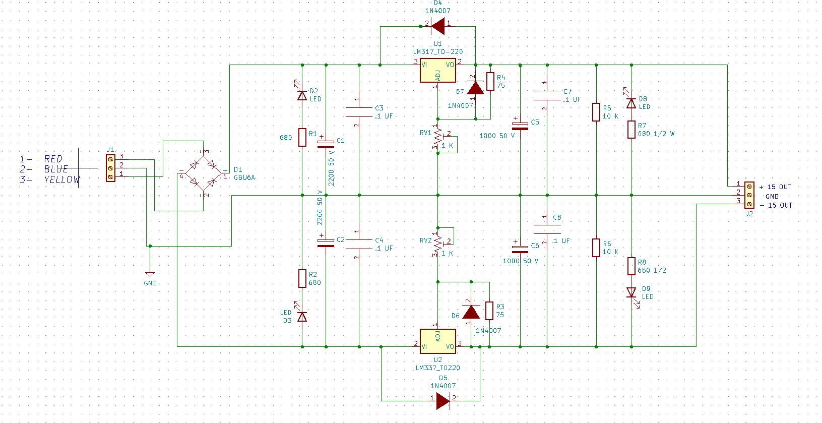
Various filters and diode protection is also in place. The 7.5 volts is sent to J-2

The input 15 V is also routed to J-2.

The LED's show voltage as present at J-2 and is a good indication that the unit is functioning properly.

This will give you outputs of +15 , -15, +7.5, and - 7.5.

We have also added a +15 V output to go to a 5 V power supply board. More on that later.

Let's breadboard this puppy and see if it works as designed. We can also make any component and value changes.

Then we can finalize the schematic and update the circuit board art if needed.

Here is what it 'should' look like. 

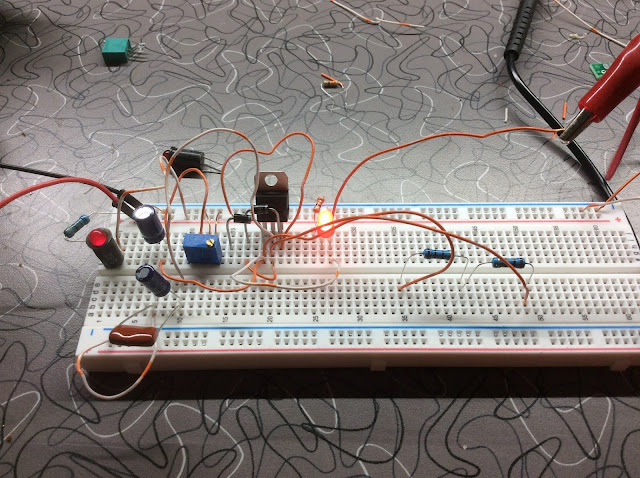
Here is the circuit for the -+ 7.5 circuit.  (I know it doesn't look very pretty, BUT will it work ??)


After a couple of false starts and playing around with resistor values, we get a perfect 7.5 Volts at the output. And YES, I need to heat sink that puppy for a long term test.


And here is the INPUT Voltage.  Congrats, we have half a power supply. Let's go get a HEAT SINK !!!!

Out to the workshop to see if I can find a piece of aluminum to use as a heat sink. I found one that was left over from a previous project.

So lets take the Voltage regulator out of the breadboard and get them mounted. (YOU MUST INSULATE THE REGULATOR FROM THE HEAT INK)


After the fact, I replaced the plastic hardware with metal.


Use a pair of pliers as a heat sink when tinning the ends and soldering the wires. A rubber band on the handle keeps the jaws tight against the regulator leads.


Here are the two regulators mounted to the temporary heat sink.


Now let's take a look at the parts list, so you can make your own power supply

C-1        22 UF 50 V

C-2        100 UF 25 V

C-3        .1 UF FILM

C-4        22 UF 50 V

C-5        .1 UF FILM

C-6        100 UF 25 V

D-1        DIODE 1N4005

D-2        DIODE 1N4005

D-3        DIODE 1N4005

D-4        DIODE 1N4005

D-5        5 MM LED

D-6        5 MM LED

D-7        5 MM LED

D-8        5 MM LED

J-1        SCREW CONNECTOR 3 POS

J-2        SCREW CONNECTOR 6 POS

J-3        SCREW CONNECTOR 2 POS

R-1        75 OHM

R-2        75 OHM

R-3        680 OHMS 1/2 WATT

R-4        680 OHMS 1/2 WATT

R-5        330 OHM 1/4 WATT

R-6        330 OHM 1/4 WATT

RV-1      TRIM POT 1 K  

RV-2      TRIM POT 1 K

U-1          LM 317  REGULATOR

U-2          LM 337 REGULATOR

  To Circuit Board or or not to Circuit Board.

I used to be a member of the 'perf board clan'. Then I tried to make my own boards at home using a Laser Printer and a modified laminating machine. The simple boards came out fine, but I never could master the complexities of more complicated boards.


Some of my first tries.


(sorry for the crappy pictures)

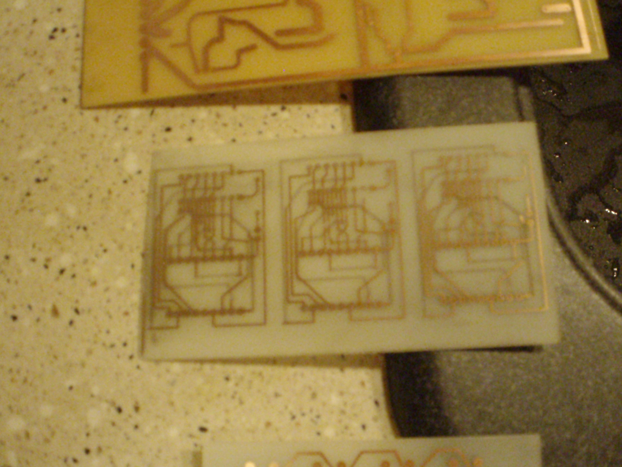
But how would I do this board ???

Fortunately, many advancements have been made, allowing us to purchase professionally made boards produced at a reasonable cost.

That's the route I am taking for this project.

There is software available to make this easier.

I use  KI-CAD .  (This will not be a tutorial in how to use KI-CAD. You are on your own.) I will say that I tested several others and thought KI-CAD to be the best. I am still learning it.


HELPFUL HINT - One bit of advice. Before you order your boards, print it out on paper. I tape it to some Styrofoam and place the parts. This way I can check footprints and clearances.

Now that we have our circuits designed, let's put together a quick proto-type that we can use while we design and build the rest of our audio console.

(NOTE:- I built a +5 volt supply for the clocks using the 7.5 Volt design. The only difference is I ended up using a 100 ohm resistor in place of R-1) 


Here is the proto-type 5 VDC supply, prior to mounting the heat sink

And something I learned much later. Diode D-3 is BACKWARDS!!!  THE BOARD WILL WORK FINE JUST
AS LONG AS YOU REVERSE WHAT THE SILKSCREEN SAYS


And a parts lists

C-1            22 UF 35 V

C-2            .1 UF FILM

C-3            .1 UF FILM

C-4            1000 UF 50 V

D-1            5 MM LED

D-2            1N4005 DIODE    

D-3            1N4005 DIODE

D-4            5 MM LED

J-1             3 LUG SCREW TERM STRIP   

J-2             3 LUG SCREW TERM STRIP  

R-1            680 OHMS 1/2 WATT

R-2            100 OHMS 1/4 WATT

R-3            330 OHMS 1/4 WATT

RV1          TRIM POT  1 K

U-1           LM317 Regulator

-----------------------------------------------------------------------------------
Here is a look at the proto type enclosure. You radio engineers will recognize the enclosure as a 2RU Rack Shelf from MIDDLE ATLANTIC , PAIRED WITH a 2 RU Rack Filler.

I don't recommend you use the Middle Atlantic units. They are GREAT but a bit pricey (50 bucks from Sweetwater) I just happened to have one on hand, so I used it. Other wise, I would have gotten some surplus aluminum and made my own.  

And, I plan on re-building this in it's own cabinet after I get the boards. Then I can strip out the Middle Atlantic rack and re-use it.

However, this made for a great prototype that we can use while building our other circuits.

At the left is the power transformer. Top right is the +/- 15 V supply with the +/- 7.5 supply below it.


And the + 5 V. supply on the right


ON/OFF switch and Fuse (hard to see) The first set of lights is the 15 V supply showing both + and - IN and OUT. Then the 7.5 supply and on the right (green LE.D.'s) is the +5 V supply


Now let's put it up on the shelf and add a barrier strip that we can use for our connections.


So there you have it. Three separate power supplies for your mixer.
-----------------------------------------------------------------------------------
UPDATE - - - This power supply has been up and running for 11 months (24/7) with no issues. I have been using it to power different proto types of our mixer design.
-----------------------------------------------------------------------------------
So now it is time to have some boards fabricated and finish up the FINAL Power Supply. I have spent some time updating the parts lists, and diagrams, so here are the files you should be using if you desire to make these Power supplies.
 
As the Great Lee Corso says "Not so fast" ...Keep reading to the end...More changes coming.

So, let's review:

First, let's take a look at the power supply input schematic.
You schematic will VARY based on your transformer. Use this schematic as a GUIDE.

I still had the original transformer from the old mixer, so I used it. 

The MOUSER part number is  546-1182G18 

All you need is a transformer with an output of 28 VOLTS and a center tap. I used a 1.5 AMP SLO BLO fuse. The output of the transformer feeds the input to the dual 15 VDC power supply.

And the +/- 15 VDC Schematic:


And the Circuit Board. (Taken from the KICAD Gerber files)


How about the FINAL Parts List for the +/- 15 Volt Supply ??

The parts are listed individually and grouped together.
-----------------------------------------------------------------------------------
AND the +/- 7.5 Supply.

Schematic:


The Gerber files:


PARTS LIST : see below

-----------------------------------------------------------------------------------
And finally the + 5 V Supply for Clocks and Accessories.


And the Parts List:


Ordering the boards was interesting. I used JLCPCB for the first time. Their Web Site and directions were easy to use. I had some errors on a couple of the Gerber files and they advised me to re-upload those.

I have to say, that the Support Staff at JLCPCB are TOP NOTCH. They worked with me and were extremely patient with this old fart.

AND here are my new boards ready for parts::::


I am starting with the +5 Volt Supply, since I have all those parts on hand.


Carefully mount your parts on the boards, checking as you proceed. Now is NOT the time to make mistakes.

Here is the completed 5 Volt board.
Here is the board we will use in our separate Clocks
And the board for the Master Power Supply. The Regulator I.C. is mounted to a temporary Heat Sink. The clip leads provide the output voltage to a Meter and to the Timer. The LED's show the Input and the Output Power.

I had an issue with the new 5 V. board that took me a while to unravel.
 
I put the board together and set the voltage. Thought I was done.... But NO. When I hooked it up to my timer, it clamped down.

After some part replacements, I realized that the Silkscreen for Diode D-3 was backwards!!. It was also backwards on the schematic.  Reversing the diode solved the issue. (I have corrected the board files)
 
While I was working on this I ran short of 1K Trim Pots. SO, I used a 2 K Trim Pot along with a 220 ohm 1/2 watt resistor in place of the 100 ohm unit. (R-2)
 
Here are the 'corrected' files for you.


And a good Parts List

Once the 5 Volt supply is completed and tested, set it aside and work on the +/- 7.5 V Supply. Don't forget to SET the voltage !!

As before,  CAREFULLY mount and solder your components.

The completed 7.5 supply board.


And the final files:

Schematic

Board Views


Parts List

The only issue on this board was I had C-5 & C-6 labeled backwards. Since they are in parallel it was not a big deal.

When completed, move on to the +/- 15 V board. Again, a diode labeled backwards caused me some confusion. I traced to issue back to the KICAD program and me choosing the wrong footprint...GEEZ..... 

A completed board.


Once it is completed and tested, it is time to rip out the old and mount in the new.

Before we mount up the new boards and re-do all the LED's,
how about a side by side comparison ???

5V

+/- 7.5V

+/- 15 V

Sorry, no side by side for the 15 V Power Supply. I had to steal some parts to finish the new one. But you get the idea.

Here is a shot of the +/- 15V supply finished and in the cabinet.


One more item to add to all of this......some way to send the voltages to the main mixer.

I chose to put together a small interface. I can wire the outputs to this interface, then send it on to the mixer.


Not much to it, is there ????  The Power supply outputs are wired to J-4. Then it connects to J1, and J2.  I will use J1 for the mixer and J-2 will go over to the bench for use with other circuits. (Until I get a Bench Supply built.)

Here are the board views. (from the Gerber files)


OK. Let's finish it up.

First, a FINAL PARTS LIST. I promise, this is it. The last one. Finish....

FINAL PARTS LIST

POWER SUPPLY

------------------------------------------------------------------------

+/- 15VDC POWER SUPPLY

2 - C1, C2 - 2200UF 50V Elect Capacitor

        JAMECO 158432

4 - C3, C4, C7, C8 - .1UF Disc Capacitor

        AMAZON .07

2 - C5, C6 - 1000UF 50V Elect Capacitor

        JAMECO 609553

1 - D1 - Diode Bridge 35V Vrms,6.0A

        MOUSER 512-GBU6A

4 - D2, D3, D8, D9 - LED 5mm

        AMAZON .07

4 - D2S, D3S, D8S, D9S - Connector 2 Pin Molex .1 2.54mm

        DIGI KEY WM19468-ND .28

        DIGI KEY WM2601-ND .18

4 - D4, D5, D6, D7 - Diode 1N4007

        JAMECO 36011

1 - J1 - 01x03 Screw Terminal 3.96mm

        JAMECO 2120655

1 - J2 - 01x04 Connector Molex 3.96mm Horiz.

        ALL ELECT CON-394

2 - R1, R2, R7, R8 - 680 ohm 1/4 WATT Resistor

        ALL ELECT 293-680

2 - R3, R4 - 75 ohm 1/4 WATT Resistor

        JAMECO 293-75

2 - R5, R6 - 10K 1/4 WATT Resistor

        ALL ELECT. 291-10K

2 - RV1, RV2 - 1K Trim Potentiometer

        ALL ELECT. MTPS 1K

1 - U1 - LM317 TO220 1.5A +35V Adjustable Linear Regulator

        JAMECO 23579

1 - U1S - 01x03 Male Connector Molex 3.96mm

        JAMECO 879887 .35

        JAMECO 463435 .15

1 - U2 - LM337 TO220 1.5A -35v Adjustable Linear Regulator

        JAMECO 23819

1 - U2S - 01x03 Male Connector Molex 3.96mm

        JAMECO 879887 .35

        JAMECO 463435 .15

1 - CB1 - CIRCUIT BOARD - JLC PRO

-------------------------------------------------------------------------

+/- 7.5 VDC POWER SUPPLY

1 - C1, C4 - 22UF 50V Elect Capacitor

        JAMECO 93739 .17

2 - C2, C6 - 100UF 25V Elect Capacitor

        JAMECO 93833 .49

2 - C3, C5 - .1UF Disc Capacitor

        AMAZON * .07

4 - D1, D2, D3, D4 - 1N4005 Diode 600V 1A General Purpose Rectifier

        ALL ELECT 1N4005 .13

4 - D5, D6, D7, D8 - LED .5mm

        AMAZON * .07

4 - D5S, D6S, D7S, D8S - Connector 2 Pin Molex .1 2.54mm

        JAMECO 232266 .15

        JAMECO 234704 .12

1 - J1 - 01x04 Connector Molex 3.96mm Horiz.

        DIGI KEY WM4642-ND .53

        DIGI KEY WM18815-ND .32

1 - J2 - 01x06 Connector Molex 3.96mm Horiz.

        DIGI KEY WM4644-ND .70

        DIGI KEY WM19505-ND .43

1 - J3 - 01x02 Screw Terminal 3.96mm Horiz.

        AMAZON *

2 - R1, R2 - 220 ohm 1/2 WATT Resistor

        JAMECO 331343 .10

2 - R3, R4 - 680 ohm 1/2 WATT Resistor

        JAMECO 661466 .10

2 - R5, R6 - 330 ohm 1/4 WATT Resistor

        JAMECO 690742 .06

2 - RV1, RV2 - 2K Trim Potentiometer

        JAMECO 240581 1.95

1 - U1 - LM317 TO220 1.5A +35V Adjustable Linear Regulator

        JAMECO 23579

1 - U1S - 01x03 Male Connector Molex 3.96mm

        JAMECO 879887 .35

        JAMECO 463435 .15

1 - U2 - LM337 TO220 1.5A -35v Adjustable Linear Regulator

        JAMECO 23819

1 - U2S - 01x03 Male Connector Molex 3.96mm

        JAMECO 879887 .35

        JAMECO 463435 .15

1 - CB2 - CIRCUIT BOARD - JLC PRO

---------------------------------------------------------

+ 5 VDC POWER SUPPLY

1 - C1 - 22UF 35V Elect Capacitor

        JAMECO 158327 .17

2 - C2, C3 - .1UF Disc Capacitor

        AMAZON * .07

2 - C4, C5 - 1000UF 50V Elect Capacitor

        JAMECO 609553 .89

2 - D1, D4 - LED .5mm

        AMAZON * .07

2 - D1, D4 - Connector 2 Pin Molex .1 2.54mm

        JAMECO 232266 .15

        JAMECO 234704 .12

2 - D2, D3 - 1N4005 Diode 600V 1A General Purpose Rectifier

        JAMECO 76988 .09

2 - J1, J2 - 01x02 Male Connector Molex 3.96mm Horiz.

        DIGI KEY WM10165-ND .46

        DIGI KEY WM18813-ND .19

1 - R1 - 680 ohm 1/2 WATT Resistor

        JAMECO 661466 .10

1 - R2 - 220 ohm 1/4 WATT Resistor

        DIDGI KEY CF14JT150RCT-ND .10

1 - R3 - 330 ohm 1/4 WATT Resistor

        JAMECO 661386 .10

1 - RV1 - 2K Trim Potentiometer

        JAMECO 240573 1.95

1 - U1 - LM317 TO220 1.5A 35V Adjustable Linear Regulator

        JAMECO 23579

1 - U1S - 01x03 Male Connector Molex 3.96mm

        JAMECO 879887 .35

        JAMECO 463435 .15

1 - 1 - CB3 - CIRCUIT BOARD - JLC PRO
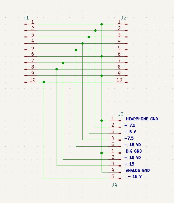
------------------------------------------------------------

INTERFACE BOARD

2 - 01 X 10 Male Connector Molex 3.96mm

        ALL ELECT HR-10 .35

        ON HAND

2 - 1X5 Connector Molex 3.96mm SCREW TERMINAL

        AMAZON *

1 - CB4 - CIRCUIT BOARD - JLC PRO

------------------------------------------------------------

CHASSIS

1 - F1 - Fuse 1.5 Slo-Blo

        ALL ELECT FSSB-1 .35

1 - F1H – FUSE HOLDER

        JAMECO 2235882 .99

1 - P1 - Wall Plug and Cable

        ON HAND

1 - SW1 – SPST

        ALL ELECT STS-135 1.55

1 - T1 - Transformer single primary, dual secondary 110/28 V

        MOUSER 1182G18 88.77


----------------------------------------------------------------
And here is the new Power Supply cabinet. I realized that the Interface Board was a bit 'large." I ended up moving the transformer down a bit and re-set one of the regulators to the right. This made room for the interface board.


To build the case, I used some of my Florida antique Heat Pine that I had salvaged. I cut it to size and glued it together. 

I used some 'splines' in the corners to add some strength.

I plan to put a metal grate on top for ventilation.

Four coats of Shellac (sanding in between coats) and 2 coats of Lacquer put on a nice finish.

Buffed out with 000 steel wool.


-----------------------------------------------------------------------------------

Things I could have done better:

I should have added one more 'spline'. It does not look even.

I probably could have put the parts closer to each other and made the boards smaller. But I had plenty of room and this was my first attempt at KICAD design.

I should have made more of an effort on making the 5V and the 7.5 V boards the SAME size. As you can see below, the 5V board is just a WEE BIT smaller.

Also I could have made the TEXT on each board the same type and size. See the difference?
The difference between the perf board version the the professionally made board is HUGE. There was nothing wrong with the perf board, it worked FLAWLESSLY for the past year or so. But I want to take this project to the NEXT level. SO on we go.!!!

Mistakes ?????   ..... Who makes 'em?????
I do !!!!!
 
From not making the 5 V and 7.5 V boards the same size, not making the fonts the same size to having a diode backwards, and 2 capacitors footprints reversed. (Altho since the caps were in parallel it was no big deal.)

I learned a great deal about the KICAD software and was VERY pleased with my first result. 

I wanted to try my hand at the easier boards first as a learning curve for the more advanced boards.  

All in all, WINNER, WINNER, CIRCUIT BOARD.....(too much Diners, Drive Inns & Dives)

And here it is, on the shelf and in use.

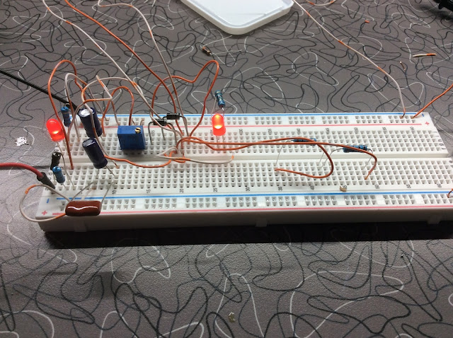
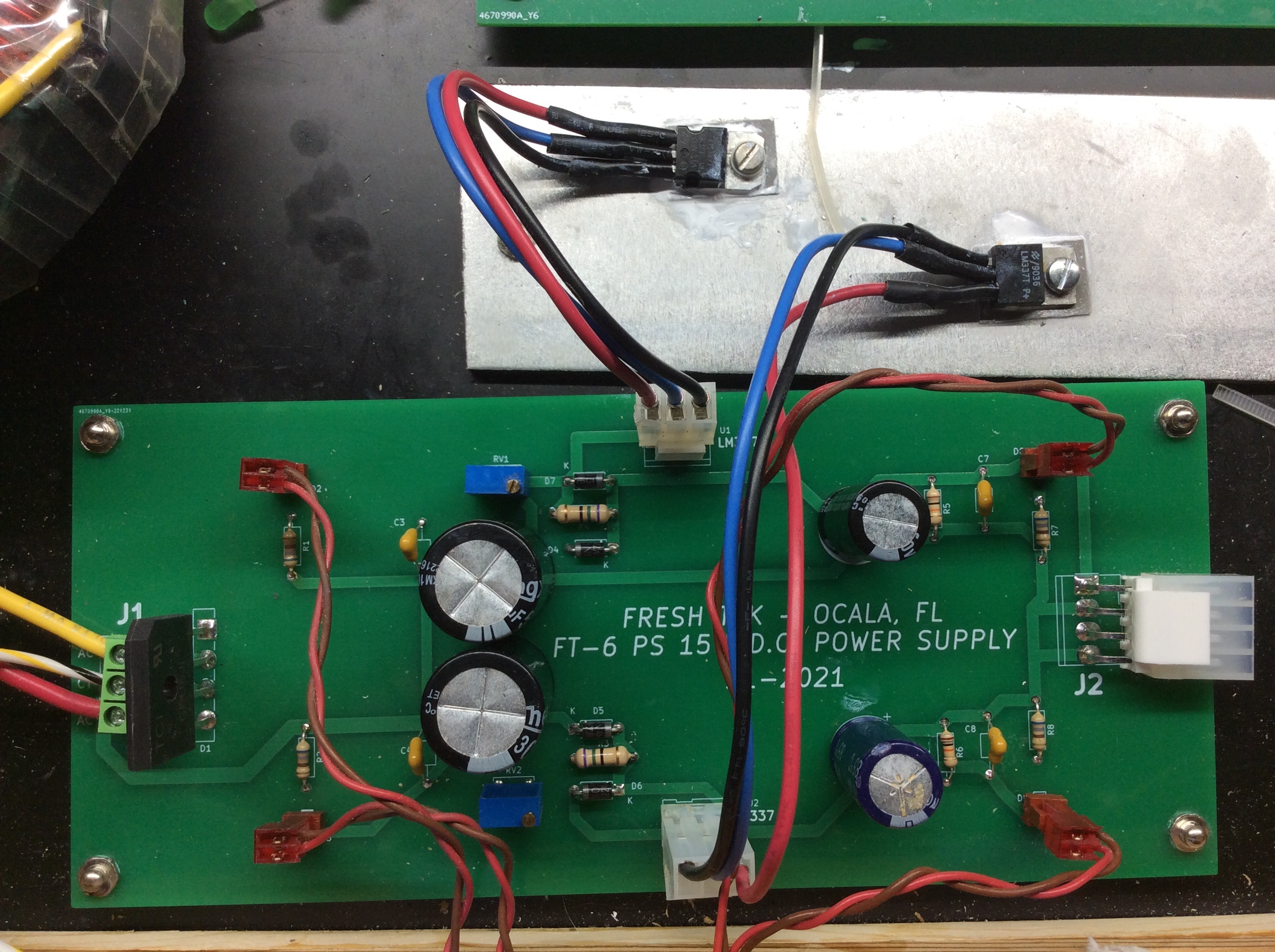
Sorry for the lousy picture. I used Super Bright LED's.


Here is a better shot of the Power Supply without the glare of the LED's.

The plan calls for a top panel with holes for ventilation. A power amp will be placed above the Power Supply. 

Not bad, huh????

Let's check our planning list. Let's mark the completed item in RED.

MIXER PLANNING

1) POWER SUPPLIES

        +/- 15 VDC XMFR 1

        +/- 7.5 V DC XMFR 1

        + 5.0 VDC 

         SCHEMATICS

        CIR BOARDS

        CABINET


2) TIMER / CLOCK 

    SEPARATE UNITS FROM MIXER DUE TO SPACE LIMITS

    12 HOUR MOD 60 MOD 60 MOD 12

    24 HOUR MOD 60 MOD 60 MOD 23

    MAIN BOARD     

    SCHEMATIC 

    CIR BOARD

    60 SEC/MIN MOD 

    SCHEMATIC 

    CIR BOARD

    23 HOUR MOD 

    SCHEMATIC 

    CIR BOARD

    12 HOUR MOD 

    SCHEMATIC 

    CIR BOARD


    TIMER UNIT

    DESIGN

    SCHEMATIC

    PROTO TYPE 

    CIR BOARD   


    RE-SET PANEL

    DESIGN

    SCHEMATIC

    PROTO TYPE 

    CIR BOARD


3) DISPLAY BOARD 

    DESIGN

    SCHEMATIC

    PROTO TYPE 

    CIR BOARD

    CABINET

    PROTO TYPE

    FINAL


4) HEADPHONE AMPLIFIER

    DESIGN

    SCHEMATIC

    PROTO TYPE

    CIRCUIT BOARD


5) CUE AMPLIFIER

    CAN ALSO USE AS A TEST AMP WHILE BUILDING AUDIO BOARDS

    DESIGN

    SCHEMATICS

    PROTO TYPE

    CIRCUIT BOARDS


6) MONITOR SELECT

    DESIGN

        AVOID OLD STYLE SWITCHES, USE DIGITAL

    SCHEMATIC

    PROTO TYPE

    CIR. BOARD


7) INPUT SELECT

    DESIGN

        AVOID OLD STYLE SWITCHES, USE DIGITAL

    SCHEMATIC

    PROTO TYPE

    CIR. BOARD


8) AUDIO INPUT BOARD

    DESIGN

            RS-12 VERSION

    SCHEMATIC

    PROTO TYPE

    CIR. BOARD


9) MONITOR BOARD

    DESIGN BASED ON MONITOR SELECT DESIGN

    SCHEMATIC

    PROTO TYPE

    CIR. BOARD


10)VU METER BOARD 

        SEPARATE UNIT ON SHELF

        ONLY USED BECAUSE IT IS ALREADY BUILT

    DESIGN

    SCHEMATIC

    PROTO TYPE 

    CIR BOARD


11) LED METERING 

    ON BOARD THE MIXER

    USE RS-12 CIRCUIT REG LED'S OR BAR GRAPHS ????

    DESIGN    

    SCHEMATICS

    PROTO TYPE

    CIRCUIT BOARD


12) POWER SUPPLY DISTRIBUTION  BOARD ??

MAY BE NEEDED WITH MULTIPLE BOARDS ??


Yeah, Number 1 is complete.

Now we can turn our attention to the timer/clock part of the project.


God speed, Mother Nature
--------------------------------
.
.
.
.
The information presented here in this web site is for personal use only and may not be
 used commercially
We make no claim as to the accuracy of the information with-in. 


No comments:

Post a Comment

ANALOG VU METER BOARD

Let's talk about the Analog VU Meter Bridge. I decided to make the Meter Bridge separate from the mixer, because of limited space inside...