Today, we are going to talk about how we get the power from the supply to the mixer.
We are building a power supply interface.
It is very straight forward.
Here is the schematic.

Power enters via J1. It is fed straight thru to J7& J8. J7 & J8 feds the audio input and output boards.
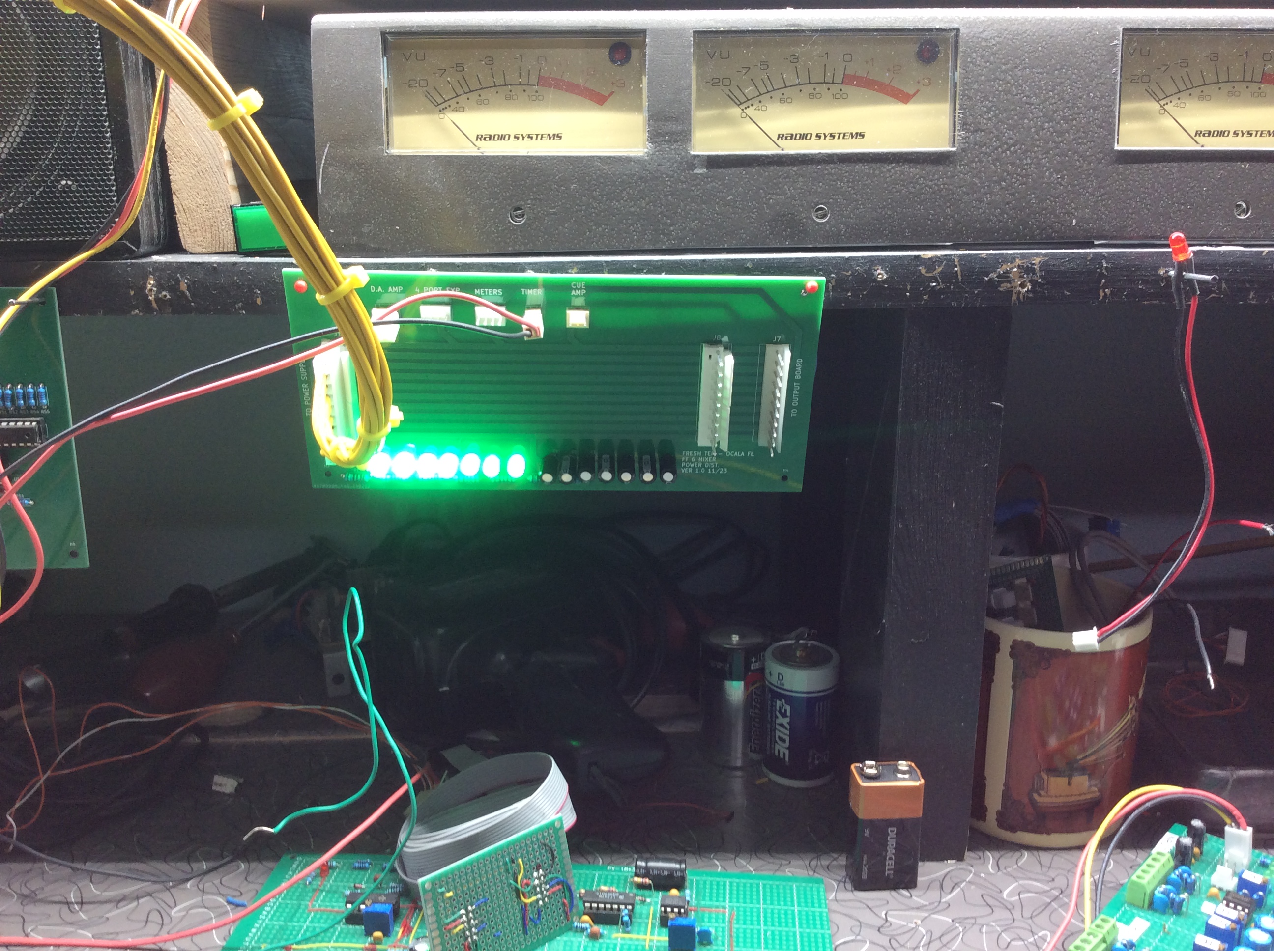
Taps are provided to power the DA AMP, 4 PORT EXPANDER, METER BRIDGE, TIMER, AND CUE & HD PHONE AMP.
Here is the designed board.


Leds shows the status of the power supply. Let's take a look at the JLCPCB board that we ordered.


Time to stuff a few parts and give it a try.


There you have it. A simple yet functioning Power Supply Interface.
I did have one small issue. When I designed this, I had the LEDS BACKWARDS in the schematic. It was easy to flip them around on the board ignoring the footprint shown.
(I did correct the schematic AND the board design.)
While was into KICAD, I went ahead and added some text to the board.
Plans are to mount this on my workshop shelf to use to power some of the temporary boards.
May not be pretty, but it will be functional.
I have yet to start building the Case for the mixer.
Now we need to figure out the LED Metering. I am having a hell of a time with this design, so back to work I go.
More later
Fresh
Next time, we look at how we make the Meters work.
.
.
.
.
.
.
The information presented here in this web site is for personal use only and may not be
used commercially
We make no claim as to the accuracy of the information with-in.


No comments:
Post a Comment