Today, we commence work on an accessory for our 6-channel Audio Mixer. This will be a TWO-part episode. 1)Design and testing a prototype and having the circuit boards made and parts installation. 2) Testing and building a cabinet.
We are incorporating a NINE-Channel Stereo Audio Equalizer.
Designed for a stereo system, it has nine 1-octave adjustments in each channel. Boost and cut limits are ±12 dB; voltage handling limit is 2 V RMS; and the total harmonic distortion is a low 0.05 percent. The frequency response of the equalizer is from 20 to 20,000 Hz (±3 dB), hum and noise is 65 dB below 1 volt RMS, input impedance is 100,000 ohms and output impedance is less than 10, ohms.
Connection to an operating audio system can be made between the preamp-out/power-amp input jacks or between the tape-out/tape monitor input jacks.
The nine gain adjustments are centered at 50, 100, 200, 400, 800, 1600, 3200, 6400, and 12,800 Hz. Although the lowest and highest frequency filters are bandpass types, their use in a feedback loop gives them a low-pass/high-pass response. The enclosure of the entire array of active bandpass filters in a feedback loop also provides low noise and distortion.
The arrangement of the potentiometer knobs for both channels on the front of the equalizer provides an accurate graphic representation of the tonal compensation. The equalizer can also integrate into an electronic musical instrument system by connecting between the preamp and the power amplifier.
As many of you are aware, we are constructing our mixer project utilizing older technology, specifically from the era when Op Amps and digital IC's dominated the electronics world.
Our project is based on an article from the May 4, 1974, issue of Popular Electronics.

Popular Electronics was an American magazine published by John August Media, LLC, and hosted at TechnicaCuriosa.com. The magazine was initiated by Ziff Davis Publishing Company in October 1954 for electronics hobbyists and experimenters. It soon became the "World's Largest-Selling Electronics Magazine."
Back in the 1950s and 1960s, every nerd like me always had a copy of the latest issue. We would spend hours poring over all the schematics and projects. And in some cases, we even made some of those projects.
Let us return to 1974, when I constructed this particular project.
It was a valuable addition to my home stereo system and provided excellent service for many years.
However, one day it stopped functioning. I had upgraded to a more compact and professional unit, and this project was sent to the scrap heap.
In retrospect, I regret having done that.
So, let's revisit this project and make it a contributing part of our quest to construct our 6 Channel Audio Mixer.
If you would like to revisit those thrilling days of Popular Electronics, you can download ALL the issues here. Make sure you have a couple of Adult Beverages and plenty of time. This web site is MASSIVE.

Let's begin with a look at our schematic.
First the Original.


FIG 1
How It Works. (Courtesy of Popular Electronics)
The schematics for one channel and the power supply are shown in Fig. 1. The input to the channel is coupled through capacitor C1 to voltage divider R1-R2. One of the two op amps in IC1 buffers the input from the voltage divider and provides a low-impedance source for the nine active filters. Each of the latter is composed of an operational amplifier (IC1 and both of IC2) with the related resistors and capacitors. The outputs of the bandpass networks are then summed in one half of IC6, whose output is fed back through R-R11. Slide potentiometers R12 through R20 vary the overall gain of the feedback loop at the operating frequency of each filter.
Since the filter circuit has unity gain 0-dB equalization settings, it is necessary to follow the summer with an amplifier made up of the second half of IC6. The amplifier also provides the signal inversion necessary to keep the input and output signals in phase.
An EQUALIZER IN-OUT (SI) is provided so that the unit can be bypassed if desired.
I have shown the basic schematic with two of the adjustment sections shown. Now we can add the other 7 sections.


Now we can design a circuit board. P.E. used two different boards (L & R) I have my boards made in China by JLC PRO. I can get 5 boards for about 25 bucks plus shipping. And I receive them in 5 days. Since JLC PCB has five-board minimum order, I am redesigning the board so that the same board design can be used for both channels. All we had to do was move the bypass switch off of the board. We do not need a power on/off switch. The final board measurement is 12 x 5 inches.
One of the changes I made to the design was to add a .1uf capacitor on each power input on each chip. (+ & - V) Most ICs need to be decoupled from their power supply, usually with a 0.1 uf capacitor between each power pin and ground.
Decoupling is usually used to remove noise and smooth power fluctuations. That is the reason you place these capacitors as close to the chip as possible.
The other major change in the design is use of the NE5532 Op Amp instead of the 5558. The 5558 used in the original was MIL-SPEC. I believe it was equivalent to 4558. However, the 4558 is hard to find. I tried a 14558 (with the same pinouts and voltage), but it failed on power up. (all the internal smoke came out) Therefore, I revised the design to use the NE5532 Op Amp.
I later found some RC4558's on AMAZON and decided to give them a try as well. More on that experiment later.


CAPACITOR ELECTROLYTIC C-01 1 UF. 50 V
CAPACITOR ELECTROLYTIC C-21 1 UF. 50 V
CAPACITOR FILM C-02 .22 UF
CAPACITOR FILM C-11 .22 UF
CAPACITOR FILM C-03 .12 UF
CAPACITOR FILM C-12 .12 UF
CAPACITOR FILM C-04 .056 UF
CAPACITOR FILM C-14 .056 UF
CAPACITOR FILM C-05 27000 PF
CAPACITOR FILM C-14 27000 PF
CAPACITOR FILM C-06 15000 PF
CAPACITOR FILM C-15 15000 PF
CAPACITOR FILM C-07 8200 PF
CAPACITOR FILM C-16 8200 PF
CAPACITOR FILM C-08 3900 PF
CAPACITOR FILM C-17 3900 PF
CAPACITOR FILM C-09 1800 PF
CAPACITOR FILM C-18 1800 PF
CAPACITOR FILM C-10 1000 PF
CAPACITOR FILM C-19 1000 PF
CAPACITOR FILM C-20 4700 PF
CAPACITOR ELECTROLYTIC C-22 10 UF 60 V
I.C. OP AMP IC-1 4558 - NE5532
I.C. OP AMP IC-2 4558 - NE5532
I.C. OP AMP IC-3 4558 - NE5532
I.C. OP AMP IC-4 4558 - NE5532
I.C. OP AMP IC-5 4558 - NE5532
I.C. OP AMP IC-6 4558 - NE5532
CONNECTOR AUDIO J-01 RCA OR MOLEX
CONNECTOR AUDIO J-02 RCA OR MOLEX
RESISTOR ¼ WATT 1 % R-01 100 K
RESISTOR ¼ WATT 1 % R-78 100K
RESISTOR ¼ WATT 1 % R-02 10K
RESISTOR ¼ WATT 1 % R-76 10K
RESISTOR ¼ WATT 1 % R-77 10K
RESISTOR ¼ WATT 1 % R-03 470
RESISTOR ¼ WATT 1 % R-04 470
RESISTOR ¼ WATT 1 % R-05 470
RESISTOR ¼ WATT 1 % R-06 470
RESISTOR ¼ WATT 1 % R-07 470
RESISTOR ¼ WATT 1 % R-08 470
RESISTOR ¼ WATT 1 % R-09 470
RESISTOR ¼ WATT 1 % R-10 470
RESISTOR ¼ WATT 1 % R-11 470
RESISTOR ¼ WATT 1 % R-21 470
RESISTOR ¼ WATT 1 % R-22 470
RESISTOR ¼ WATT 1 % R-23 470
RESISTOR ¼ WATT 1 % R-24 470
RESISTOR ¼ WATT 1 % R-25 470
RESISTOR ¼ WATT 1 % R-26 470
RESISTOR ¼ WATT 1 % R-27 470
RESISTOR ¼ WATT 1 % R-28 470
RESISTOR ¼ WATT 1 % R-29 470
POTENTIOMETER SLIDE POT R-12 10 K
POTENTIOMETER SLIDE POT R-13 10 K
POTENTIOMETER SLIDE POT R-14 10 K
POTENTIOMETER SLIDE POT R-15 10 K
POTENTIOMETER SLIDE POT R-16 10 K
POTENTIOMETER SLIDE POT R-17 10 K
POTENTIOMETER SLIDE POT R-18 10 K
POTENTIOMETER SLIDE POT R-19 10 K
POTENTIOMETER SLIDE POT R-20 10 K
I found the slide pots on AMAZON
RESISTOR ¼ WATT 1 % R-30 3900
RESISTOR ¼ WATT 1 % R-31 3900
RESISTOR ¼ WATT 1 % R-32 3900
RESISTOR ¼ WATT 1 % R-33 3900
RESISTOR ¼ WATT 1 % R-34 3900
RESISTOR ¼ WATT 1 % R-35 3900
RESISTOR ¼ WATT 1 % R-36 3900
RESISTOR ¼ WATT 1 % R-37 3900
RESISTOR ¼ WATT 1 % R-38 3900
RESISTOR ¼ WATT 1 % R-39 47 K
RESISTOR ¼ WATT 1 % R-40 47 K
RESISTOR ¼ WATT 1 % R-41 47 K
RESISTOR ¼ WATT 1 % R-42 47 K
RESISTOR ¼ WATT 1 % R-43 47 K
RESISTOR ¼ WATT 1 % R-44 47 K
RESISTOR ¼ WATT 1 % R-45 47 K
RESISTOR ¼ WATT 1 % R-46 47 K
RESISTOR ¼ WATT 1 % R-47 47 K
RESISTOR ¼ WATT 1 % R-48 6800
RESISTOR ¼ WATT 1 % R-49 6800
RESISTOR ¼ WATT 1 % R-50 6800
RESISTOR ¼ WATT 1 % R-51 6800
RESISTOR ¼ WATT 1 % R-52 6800
RESISTOR ¼ WATT 1 % R-53 6800
RESISTOR ¼ WATT 1 % R-54 6800
RESISTOR ¼ WATT 1 % R-55 6800
RESISTOR ¼ WATT 1 % R-56 6800
RESISTOR ¼ WATT 1 % R-57 680
RESISTOR ¼ WATT 1 % R-58 680
RESISTOR ¼ WATT 1 % R-59 680
RESISTOR ¼ WATT 1 % R-60 680
RESISTOR ¼ WATT 1 % R-61 680
RESISTOR ¼ WATT 1 % R-62 680
RESISTOR ¼ WATT 1 % R-63 680
RESISTOR ¼ WATT 1 % R-64 680
RESISTOR ¼ WATT 1 % R-65 680
RESISTOR ¼ WATT 1 % R-66 22 K
RESISTOR ¼ WATT 1 % R-67 22 K
RESISTOR ¼ WATT 1 % R-68 22 K
RESISTOR ¼ WATT 1 % R-69 22 K
RESISTOR ¼ WATT 1 % R-70 22 K
RESISTOR ¼ WATT 1 % R-71 22 K
RESISTOR ¼ WATT 1 % R-72 22 K
RESISTOR ¼ WATT 1 % R-74 22 K
RESISTOR ¼ WATT 1 % R-74 22 K
SWITCH D.P.D.T. S1
Found these on AMAZON (YOU ONLY NEED ONE)
CONNECTOR MOLEX J-03 3 PIN
CONNECTOR MOLEX J-04 3 PIN
CONNECTOR MOLEX J-05 3 PIN


Now we can order some circuit boards from China. Too save on shipping I usually order boards for other parts of the project at the same time. (I.E. Controller boards for my digital clock project - WATCH THE SPACE FOR THAT ONE)

So, the design is done, and the prototype works. It is time for a break.

As soon as I get the boards, we will resume this project. Until then, we'll go out to the shop and make some man glitter. (If it warms up)
One item I neglected to mention previously was the bypass switch.
Below is the diagram of the switch.

And the final Board version.


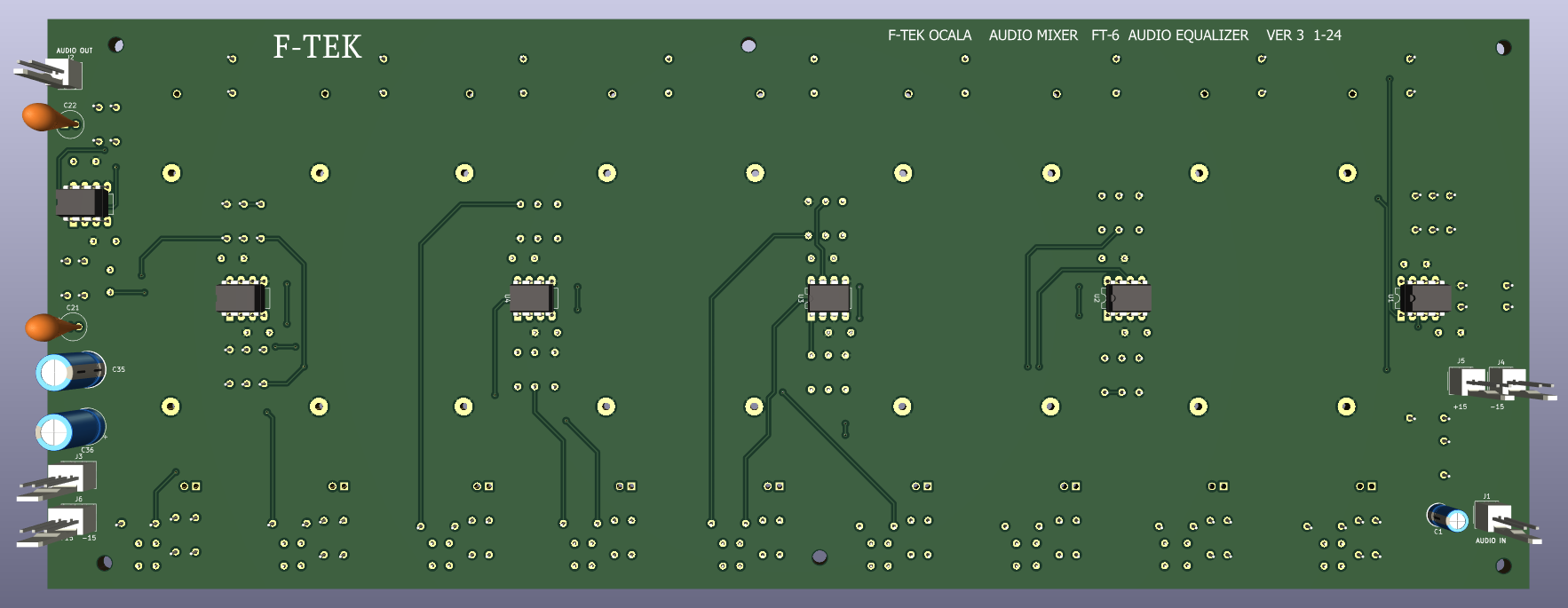


And it works!!!!


No comments:
Post a Comment