Wednesday, June 5, 2024

ANALOG VU METER BOARD

Let's talk about the Analog VU Meter Bridge. I decided to make the Meter Bridge separate from the mixer, because of limited space inside my Ham Radio room. I am placing the unit right above my computer monitor and Digital Clocks.

This board is designed to accept the Mixer Buss output and drive Analog VU Meters along with a PEAK LED indicator.

A SIMPLE EXPANATION

The audio enters the board via J-1 and is fed to an LM5532 OP AMP. The OP Amp feeds a full wave rectifier to convert it to a low voltage that feeds the VU Meter. The signal then continues to an LM339 Quad Differential Comparator that drives the LED Peak indicator. 

MORE DETAILED

Integrated circuit U2A, diodes Dl thru D4 and the associated resistors convert the balanced left program channel output to a floating D.C. voltage to drive the left program VU meter. Therefore, the effects of loading the console output or erroneously grounding one of the console outputs will be reflected on the VU meter. Trimmer VR2 provides “0” VU adjustment for a range of console outputs. differential amplifier U2B converts the meter voltage from floating to single ended prior to applying the voltage to U15A. Integrated circuit U15A functions as a peak detector with the trip point adjusted by VR12.

When the positive peak of the audio signal (applied to U15 pin 4) becomes more positive than the reference set by VR12 the output of U15A will go to -15 volts and in turn the output of U15B will go to -15 volts and illuminate the peak LED. At the conclusion of the peak U15 pin 4 will fall to lower potential than the reference set by VR12, and the output of U15A (which is an open collector) will allow C59 to be charged by R115. When the potential at U15 pin 9 is more positive than the reference at U15 pin 8 the output of U15 B will go high, and the LED will extinguish. Capacitor C59 and resistor R115 act as a .5 second peak stretcher which allows the LED to properly illuminate.

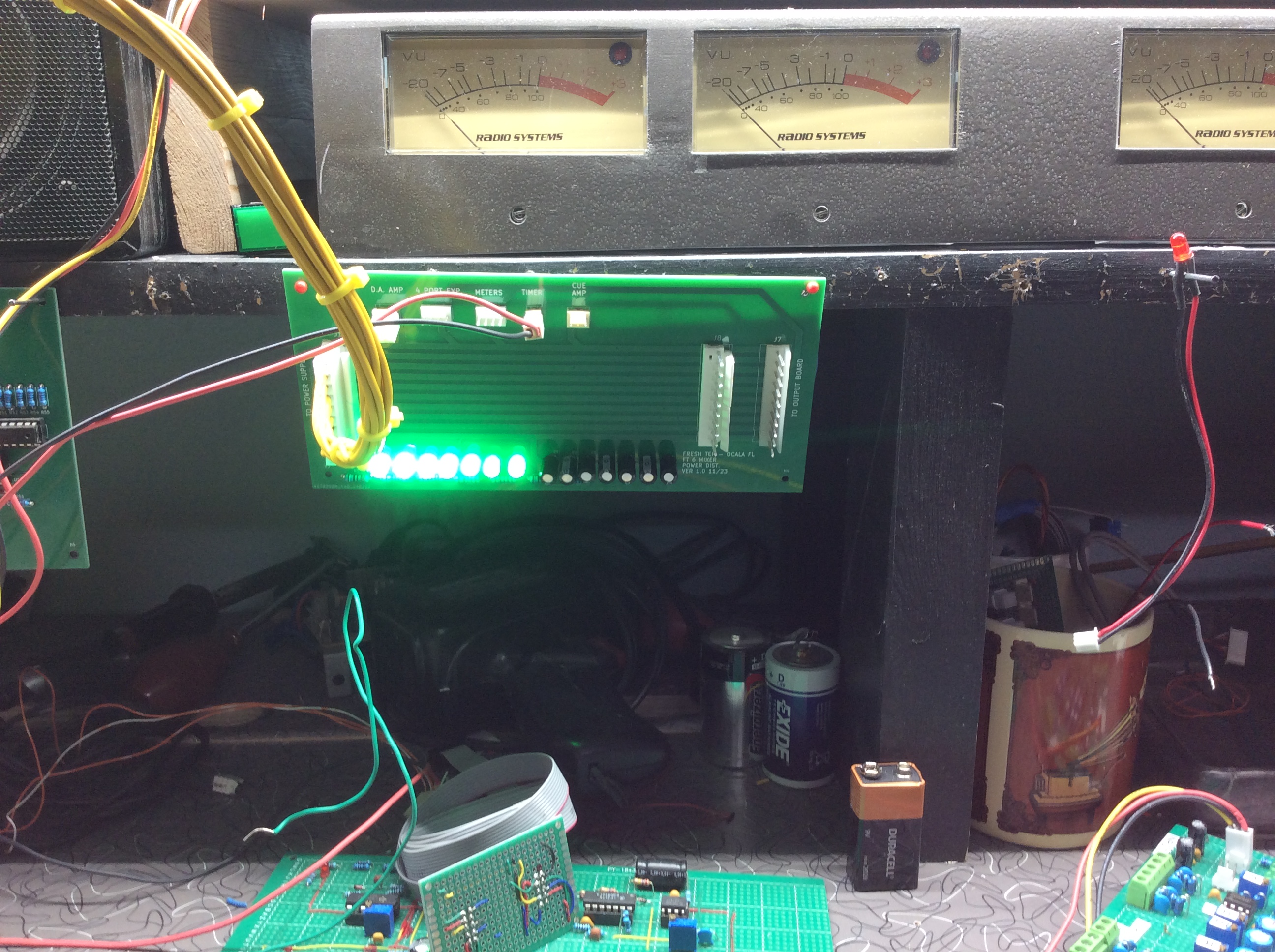
The meters I used are 'surplus' RADIO SYSTEMS meters, that I pulled from a large 24 channel mixer I bought for spare parts.

The unit will also reduce my parts count on the Output Board.

So, let's get to it.

Here is the schematic: 

PROGRAM AND AUDITION 

MONO AND POWER

And the designed circuit board:


I also did a prototype for testing:
Sorry for the crappy photo.

After building the prototype, I decided putting the trim POTS on the bottom of the board made drawing the traces more difficult. So, I placed the 'peak' controls closer to the IC they are connected to. I can slide the board out to get to them. You will see that when we make the cabinet. (I am hoping the settings are a 'set and forget' type.)

I used the meters from the Original Meter Bridge I built around 2008. I removed it from the cabinet and placed it on a shelf until I get the rest of it completed. 

Here is the original cabinet that sat on top of my original mixer.

A temporary set up.

Here I am testing not only the VU Meters, but the LED meters AND the 12-hour clock that is ready for a cabinet. (AS soon as I finish the final 24-hour version) 


HERE IS THE PARTS LIST FOR THE ANALOG VU BOARD:


CAPACITOR DISC C-001 0.1

CAPACITOR DISC C-002 0.1

CAPACITOR DISC C-003 0.1

CAPACITOR DISC C-004 0.1

CAPACITOR DISC C-005 0.1

CAPACITOR DISC C-006 0.1

CAPACITOR DISC C-007 0.1

CAPACITOR DISC C-008 0.1

CAPACITOR DISC C-009 0.1

CAPACITOR DISC C-010 0.1

CAPACITOR DISC C-030 0.1

CAPACITOR DISC C-058 0.1

CAPACITOR DISC C-059 0.1

CAPACITOR DISC C-060 0.1

CAPACITOR DISC C-062 0.1

CAPACITOR DISC C-202 0.1

CAPACITOR DISC C-203 0.1

CAPACITOR DISC C-206 0.1

CAPACITOR DISC C-207 0.1

RESISTOR FILM R-102 1.8 K ¼ W 1%

RESISTOR FILM R-110 1.8 K ¼ W 1%

RESISTOR FILM R-111 1.8 K ¼ W 1%

RESISTOR FILM R-112 1.8 K ¼ W 1%

RESISTOR FILM R-113 1.8 K ¼ W 1%

POTENTIOMETER TRIM RV-002 10 K

POTENTIOMETER TRIM RV-003 10 K

POTENTIOMETER TRIM RV-004 10 K

POTENTIOMETER TRIM RV-005 10 K

POTENTIOMETER TRIM RV-006 10 K

POTENTIOMETER TRIM RV-012 10 K

POTENTIOMETER TRIM RV-013 10 K

POTENTIOMETER TRIM RV-014 10 K

POTENTIOMETER TRIM RV-015 10 K

POTENTIOMETER TRIM RV-016 10 K

CAPACITOR FILM C-016 10 PF

CAPACITOR FILM C-017 10 PF

CAPACITOR FILM C-019 10 PF

CAPACITOR FILM C-020 10 PF

CAPACITOR FILM C-022 10 PF

CAPACITOR FILM C-023 10 PF

CAPACITOR FILM C-025 10 PF

CAPACITOR FILM C-026 10 PF

CAPACITOR FILM C-028 10 PF

CAPACITOR FILM C-029 10 PF

RESISTOR FILM R-012 10.2 K ¼ W 1%

RESISTOR FILM R-013 10.2 K ¼ W 1%

RESISTOR FILM R-017 10.2 K ¼ W 1%

RESISTOR FILM R-018 10.2 K ¼ W 1%

RESISTOR FILM R-019 10.2 K ¼ W 1%

RESISTOR FILM R-020 10.2 K ¼ W 1%

RESISTOR FILM R-021 10.2 K ¼ W 1%

RESISTOR FILM R-023 10.2 K ¼ W 1%

RESISTOR FILM R-024 10.2 K ¼ W 1%

RESISTOR FILM R-028 10.2 K ¼ W 1%

RESISTOR FILM R-029 10.2 K ¼ W 1%

RESISTOR FILM R-030 10.2 K ¼ W 1%

RESISTOR FILM R-031 10.2 K ¼ W 1%

RESISTOR FILM R-032 10.2 K ¼ W 1%

RESISTOR FILM R-034 10.2 K ¼ W 1%

RESISTOR FILM R-035 10.2 K ¼ W 1%

RESISTOR FILM R-039 10.2 K ¼ W 1%

RESISTOR FILM R-040 10.2 K ¼ W 1%

RESISTOR FILM R-041 10.2 K ¼ W 1%

RESISTOR FILM R-042 10.2 K ¼ W 1%

RESISTOR FILM R-043 10.2 K ¼ W 1%

RESISTOR FILM R-045 10.2 K ¼ W 1%

RESISTOR FILM R-046 10.2 K ¼ W 1%

RESISTOR FILM R-050 10.2 K ¼ W 1%

RESISTOR FILM R-051 10.2 K ¼ W 1%

RESISTOR FILM R-052 10.2 K ¼ W 1%

RESISTOR FILM R-053 10.2 K ¼ W 1%

RESISTOR FILM R-054 10.2 K ¼ W 1%

RESISTOR FILM R-056 10.2 K ¼ W 1%

RESISTOR FILM R-057 10.2 K ¼ W 1%

RESISTOR FILM R-061 10.2 K ¼ W 1%

RESISTOR FILM R-062 10.2 K ¼ W 1%

RESISTOR FILM R-063 10.2 K ¼ W 1%

RESISTOR FILM R-064 10.2 K ¼ W 1%

RESISTOR FILM R-065 10.2 K ¼ W 1%

RESISTOR FILM R-016 100 K ¼ W 1%

RESISTOR FILM R-027 100 K ¼ W 1%

RESISTOR FILM R-038 100 K ¼ W 1%

RESISTOR FILM R-049 100 K ¼ W 1%

RESISTOR FILM R-060 100 K ¼ W 1%

RESISTOR FILM R-011 110 ¼ W 1%

RESISTOR FILM R-022 110 ¼ W 1%

RESISTOR FILM R-033 110 ¼ W 1%

RESISTOR FILM R-044 110 ¼ W 1%

RESISTOR FILM R-055 110 ¼ W 1%

SOCKET I.C.         U-011S 14 PIN DIP

SOCKET I.C.         U-015S 14 PIN DIP

SOCKET I.C.         U-016S 14 PIN DIP

DIODE GERMANIUM D-001 1N270

DIODE GERMANIUM D-002 1N270

DIODE GERMANIUM D-003 1N270

DIODE GERMANIUM D-004 1N270

DIODE GERMANIUM D-005 1N270

DIODE GERMANIUM D-006 1N270

DIODE GERMANIUM D-007 1N270

DIODE GERMANIUM D-008 1N270

DIODE GERMANIUM D-009 1N270

DIODE GERMANIUM D-010 1N270

DIODE GERMANIUM D-011 1N270

DIODE GERMANIUM D-012 1N270

DIODE GERMANIUM D-013 1N270

DIODE GERMANIUM D-014 1N270

DIODE GERMANIUM D-015 1N270

DIODE GERMANIUM D-016 1N270

DIODE GERMANIUM D-017 1N270

DIODE GERMANIUM D-018 1N270

DIODE GERMANIUM D-019 1N270

DIODE GERMANIUM D-020 1N270

RESISTOR FILM R-014 20 K ¼ W 1%

RESISTOR FILM R-015 20 K ¼ W 1%

RESISTOR FILM R-025 20 K ¼ W 1%

RESISTOR FILM R-026 20 K ¼ W 1%

RESISTOR FILM R-036 20 K ¼ W 1%

RESISTOR FILM R-037 20 K ¼ W 1%

RESISTOR FILM R-047 20 K ¼ W 1%

RESISTOR FILM R-048 20 K ¼ W 1%

RESISTOR FILM R-058 20 K ¼ W 1%

RESISTOR FILM R-059 20 K ¼ W 1%

CAPACITOR ELECTROLYTIC C-201 220 UF @ 50 V

CAPACITOR ELECTROLYTIC C-204 220 UF @ 50 V

CAPACITOR ELECTROLYTIC C-205 220 UF @ 50 V

CAPACITOR ELECTROLYTIC C-208 220 UF @ 50 V

CONNECTOR IDC J-001 2X7 ODD/EVEN

RESISTOR FILM D-201 330 ½ W 1%

RESISTOR FILM R-200 330 ½ W 1%

RESISTOR FILM R-202 330 ½ W 1%

RESISTOR FILM R-203 330 ½ W 1%

RESISTOR FILM R-114 4.7 MEG ¼ W 1%

RESISTOR FILM R-115 4.7 MEG ¼ W 1%

RESISTOR FILM R-116 4.7 MEG ¼ W 1%

RESISTOR FILM R-117 4.7 MEG ¼ W 1%

RESISTOR FILM R-118 4.7 MEG ¼ W 1%

CONNECTOR MOLEX .1 J-001 7 PIN .1

CONNECTOR MOLEX .1 J-400 7 PIN .1

SOCKET I.C. U-002S 8 PIN DIP

SOCKET I.C. U-003S 8 PIN DIP

SOCKET I.C. U-004S 8 PIN DIP

SOCKET I.C. U-005S 8 PIN DIP

SOCKET I.C. U-006S 8 PIN DIP

LED 5MM D-201 GREEN LED

LED 5MM D-202 GREEN LED

LED 5MM D-203 GREEN LED

LED 5MM D-204 GREEN LED

I.C. COMPARATOR U-015 LM339

I.C. COMPARATOR U-016 LM339

I.C. COMPARATOR U-017 LM339

I.C. OP AMP U-002 NE5532

I.C. OP AMP U-003 NE5532

I.C. OP AMP U-004 NE5532

I.C. OP AMP U-005 NE5532

I.C. OP AMP U-006 NE5532

METER VU TYPE VU-001

METER VU TYPE VU-002

METER VU TYPE VU-003

METER VU TYPE VU-004

METER VU TYPE VU-005

BOARD JLC PRO

----------------------------------------------------------------------------------

Now we order the boards and wait.

(Insert Jeopardy Theme song here)

OK, here is the new board.

Let's start stuffing the board with parts.

Here is the board with a few components installed.

The schematic calls for the rectifier diodes to be 1n270. These get a bit pricey ($1.50 each) if you do a one channel mockup, then a full proto board, and a final board.

So, I tried the less expensive 1n34a Germanium diodes ($.30), and they worked just as well as the 1n270. Feel free to use either unit.

(NOTE: Prices may vary, but you get the idea.)

I started with the power input circuits and made sure it worked. I then moved onto Left Program circuit. I wired it up to the Peak circuit. The meter circuit worked well, so I moved onto the PEAK circuit.

You get the idea. Do this one channel at a time, verifying the circuits as you go.

Continue on.

And here it is, the completed and working VU Meter Board.

Before we move onto a cabinet, I would like to re-visit the LED Meters that I was working on. I have had a hell of a time getting these to work properly but I may want to put the LED and the ANALOG Meters in the same cabinet. 

So, we will set this aside, get the LED version to work, then do a separate blog on the cabinet.

See you then!!!


.
.
.
.
.
.

The information presented here in this web site is for personal use only and may not be
 used commercially
We make no claim as to the accuracy of the information with-in. 


Tuesday, March 26, 2024

POWER DISTRABUTION

Today, we are going to talk about how we get the power from the supply to the mixer.

We are building a power supply interface.

It is very straight forward.

Here is the schematic.

Power enters via J1. It is fed straight thru to J7& J8. J7 & J8 feds the audio input and output boards.

Taps are provided to power the DA AMP, 4 PORT EXPANDER, METER BRIDGE, TIMER, AND CUE & HD PHONE AMP.

Here is the designed board.


Leds shows the status of the power supply. Let's take a look at the JLCPCB board that we ordered.


Time to stuff a few parts and give it a try.

Everything works!!!!
Here is a shot of the board with power turned off.

There you have it. A simple yet functioning Power Supply Interface.

I did have one small issue. When I designed this, I had the LEDS BACKWARDS in the schematic. It was easy to flip them around on the board ignoring the footprint shown.

(I did correct the schematic AND the board design.)

While was into KICAD, I went ahead and added some text to the board.

Plans are to mount this on my workshop shelf to use to power some of the temporary boards. 
May not be pretty, but it will be functional.

I have yet to start building the Case for the mixer.

Now we need to figure out the LED Metering. I am having a hell of a time with this design, so back to work I go.

More later

Fresh


Tuesday, January 2, 2024

THE AUDIO DISTRIBUTION AMPLIFIER

 And we are back hard at work on our FT-6, 6 Channel Audio Mixer.

Today we take a look at audio distribution. 

Back in the day, I made LARGE D.A. Amplifiers.

It was the first time I did my own metal work. I thought they came out nice.


They gave me 8 Channels of Audio for Program, Audition and MONO.

For this 'scaled down' version I don't need that many outputs so we are using a design that will fit into the Mixer. (Thus, saving us more space.) The design comes right out of the Radio Systems Manual.


Here is a closer look at just one channel (The rest are the same.)


The design is probably the easiest we will tackle building this project. Simple IC's and if you plan correctly, it will work extremely well.

We need an output to run to the computer's audio editing software. And another output to drive some digital VU Meters I have planned. (We will also use standard VU Meters as well.)

Why do I need two versions of VU Metering? I don't, but I have a ton of Analog VU Meters I can use.

Back in the day I built some digital units and really liked them. 
Yeah, it's a crappy picture. It was the early years of digital cameras.
But you can get the idea.  Cool, aren't they?

So why not?

But back to the DA Amp.

We thought about bypassing the prototype here and going direct to a manufactured board. But I do not trust myself, and a protype helps ferret out mistakes BEFORE I spend money on an expensive board from JLCPCB.


Here is your PARTS LIST

C-01 CAPACITOR DISC 100 PF 500V
C-02 CAPACITOR DISC 100 PF 500V
C-03 CAPACITOR DISC 100 PF 500V
C-04 CAPACITOR DISC 100 PF 500V
C-05 CAPACITOR DISC 47 PF 500V
C-06 CAPACITOR DISC 47 PF 500V
C-07 CAPACITOR N.P. 100 UF 16V RADIAL
C-08 CAPACITOR N.P. 100 UF 16V RADIAL
C-09 CAPACITOR N.P. 100 UF 16V RADIAL
C-10 CAPACITOR N.P. 100 UF 16V RADIAL
C-11 CAPACITOR ELECT. 15 UF 35V RADIAL
C-12 CAPACITOR ELECT. 15 UF 35V RADIAL
C-13 CAPACITOR FILM .1 UF 50V
C-14 CAPACITOR FILM .1 UF 50V
C-15 CAPACITOR DISC 47 PF 500V
C-16 CAPACITOR DISC 47 PF 500V
C-17 CAPACITOR DISC 47 PF 500V
C-18 CAPACITOR DISC 47 PF 500V
C-19 CAPACITOR FILM .1 UF 50V
C-20 CAPACITOR FILM .1 UF 50V
C-21 CAPACITOR FILM .0022 UF 50V
C-22 CAPACITOR FILM .0022 UF 50V
C-23 CAPACITOR FILM .0022 UF 50V
C-24 CAPACITOR FILM .0022 UF 50V
C-25 CAPACITOR FILM .0022 UF 50V
C-26 CAPACITOR FILM .0022 UF 50V
C-27 CAPACITOR FILM .0022 UF 50V
C-28 CAPACITOR FILM .0022 UF 50V
C-29 CAPACITOR FILM .1 UF 50V
C-30 CAPACITOR FILM .1 UF 50V
C-31 CAPACITOR FILM .1 UF 50V
C-32 CAPACITOR FILM .1 UF 50V
C-33 CAPACITOR FILM .1 UF 50V
C-34 CAPACITOR FILM .1 UF 50V
C-35 CAPACITOR FILM .1 UF 50V
C-36 CAPACITOR FILM .1 UF 50V
C-37 CAPACITOR FILM .1 UF 50V
C-38 CAPACITOR FILM .1 UF 50V
C-39 CAPACITOR FILM .1 UF 50V
C-40 CAPACITOR FILM .1 UF 50V
C-41 CAPACITOR FILM .1 UF 50V
C-42 CAPACITOR FILM .1 UF 50V
C-43 CAPACITOR FILM .1 UF 50V
C-44 CAPACITOR FILM .1 UF 50V
C-45 CAPACITOR FILM .1 UF 50V
C-46 CAPACITOR FILM .1 UF 50V
C-51 CAPACITOR DISC 100 PF 500V
C-52 CAPACITOR DISC 100 PF 500V
C-53 CAPACITOR DISC 100 PF 500V
C-54 CAPACITOR DISC 100 PF 500V
C-54 CAPACITOR DISC 47 PF 500V
C-55 CAPACITOR DISC 47 PF 500V
C-56 CAPACITOR DISC 47 PF 500V
C-57 CAPACITOR N.P. 100 UF 16V RADIAL
C-58 CAPACITOR N.P. 100 UF 16V RADIAL
C-59 CAPACITOR N.P. 100 UF 16V RADIAL
C-60 CAPACITOR N.P. 100 UF 16V RADIAL
C-61 CAPACITOR DISC 47 PF 500V
C-62 CAPACITOR DISC 47 PF 500V
C-63 CAPACITOR DISC 47 PF 500V
C-65 CAPACITOR FILM .0022 UF 50V
C-66 CAPACITOR FILM .0022 UF 50V
C-67 CAPACITOR FILM .0022 UF 50V
C-68 CAPACITOR FILM .0022 UF 50V
C-69 CAPACITOR FILM .0022 UF 50V
C-70 CAPACITOR FILM .0022 UF 50V
C-71 CAPACITOR FILM .0022 UF 50V
C-72 CAPACITOR FILM .0022 UF 50V
D-01 LED 3 MM
D-02 LED 3 MM
J-1 HEADER MOLEX 3 PIN - .1
J-2 HEADER MOLEX 3 PIN - .1
R-001 RESISTOR FILM 5.11 K ¼ W 1%
R-002 RESISTOR FILM 5.11 K ¼ W 1%
R-003 RESISTOR FILM 5.11 K ¼ W 1%
R-004 RESISTOR FILM 5.11 K ¼ W 1%
R-005 RESISTOR FILM 10 K ¼ W 1%
R-006 RESISTOR FILM 10 K ¼ W 1%
R-007 RESISTOR FILM 10.2 K ¼ W 1%
R-008 RESISTOR FILM 10.2 K ¼ W 1%
R-009 RESISTOR FILM 10.2 K ¼ W 1%
R-010 RESISTOR FILM 10.2 K ¼ W 1%
R-011 RESISTOR FILM 10.2 K ¼ W 1%
R-012 RESISTOR FILM 10.2 K ¼ W 1%
R-013 RESISTOR FILM 10.2 K ¼ W 1%
R-014 RESISTOR FILM 10.2 K ¼ W 1%
R-015 RESISTOR FILM 1.50 K 1/4W 1%
R-016 RESISTOR FILM 1.50 K 1/4W 1%
R-017 RESISTOR FILM 1.50 K 1/4W 1%
R-018 RESISTOR FILM 1.50 K 1/4W 1%
R-019 RESISTOR FILM 10.2 K ¼ W 1%
R-020 RESISTOR FILM 10.2 K ¼ W 1%
R-021 RESISTOR FILM 10.2 K ¼ W 1%
R-022 RESISTOR FILM 10.2 K ¼ W 1%
R-023 RESISTOR FILM 10.2 K ¼ W 1%
R-024 RESISTOR FILM 10.2 K ¼ W 1%
R-025 RESISTOR FILM 10.2 K ¼ W 1%
R-026 RESISTOR FILM 10.2 K ¼ W 1%
R-027 RESISTOR FILM 46.4 ¼ W 1%
R-028 RESISTOR FILM 46.4 ¼ W 1%
R-029 RESISTOR FILM 10.2 K ¼ W 1%
R-030 RESISTOR FILM 10.2 K ¼ W 1%
R-031 RESISTOR FILM 10.2 K ¼ W 1%
R-032 RESISTOR FILM 10.2 K ¼ W 1%
R-033 RESISTOR FILM 46.4 ¼ W 1%
R-034 RESISTOR FILM 46.4 ¼ W 1%
R-035 RESISTOR FILM 46.4 ¼ W 1%
R-036 RESISTOR FILM 46.4 ¼ W 1%
R-037 RESISTOR FILM 750 ½ W
R-038 RESISTOR FILM 46.4 ¼ W 1%
R-039 RESISTOR FILM 46.4 ¼ W 1%
R-040 RESISTOR FILM 750 ½ W
R-079 RESISTOR FILM 5.11 K ¼ W 1%
R-080 RESISTOR FILM 5.11 K ¼ W 1%
R-081 RESISTOR FILM 5.11 K ¼ W 1%
R-082 RESISTOR FILM 5.11 K ¼ W 1%
R-083 RESISTOR FILM 10 K ¼ W 1%
R-084 RESISTOR FILM 10 K ¼ W 1%
R-085 RESISTOR FILM 10.2 K ¼ W 1%
R-086 RESISTOR FILM 10.2 K ¼ W 1%
R-087 RESISTOR FILM 10.2 K ¼ W 1%
R-088 RESISTOR FILM 10.2 K ¼ W 1%
R-089 RESISTOR FILM 10.2 K ¼ W 1%
R-090 RESISTOR FILM 10.2 K ¼ W 1%
R-091 RESISTOR FILM 10.2 K ¼ W 1%
R-092 RESISTOR FILM 10.2 K ¼ W 1%
R-093 RESISTOR FILM 1.50 K 1/4W 1%
R-094 RESISTOR FILM 1.50 K 1/4W 1%
R-095 RESISTOR FILM 1.50 K 1/4W 1%
R-096 RESISTOR FILM 1.50 K 1/4W 1%
R-097 RESISTOR FILM 10.2 K ¼ W 1%
R-098 RESISTOR FILM 10.2 K ¼ W 1%
R-099 RESISTOR FILM 10.2 K ¼ W 1%
R-100 RESISTOR FILM 10.2 K ¼ W 1%
R-101 RESISTOR FILM 10.2 K ¼ W 1%
R-102 RESISTOR FILM 10.2 K ¼ W 1%
R-103 RESISTOR FILM 10.2 K ¼ W 1%
R-104 RESISTOR FILM 10.2 K ¼ W 1%
R-105 RESISTOR FILM 46.4 ¼ W 1%
R-106 RESISTOR FILM 46.4 ¼ W 1%
R-107 RESISTOR FILM 10.2 K ¼ W 1%
R-108 RESISTOR FILM 10.2 K ¼ W 1%
R-109 RESISTOR FILM 10.2 K ¼ W 1%
R-110 RESISTOR FILM 10.2 K ¼ W 1%
R-111 RESISTOR FILM 46.4 ¼ W 1%
R-112 RESISTOR FILM 46.4 ¼ W 1%
R-113 RESISTOR FILM 46.4 ¼ W 1%
R-114 RESISTOR FILM 46.4 ¼ W 1%
R-115 RESISTOR FILM 46.4 ¼ W 1%
R-116 RESISTOR FILM 46.4 ¼ W 1%
RV-01 TRIM POT TOP ADJ. 10 K
RV-02 TRIM POT TOP ADJ. 10 K
RV-03 TRIM POT TOP ADJ. 10 K
RV-04 TRIM POT TOP ADJ. 10 K
RV-09 TRIM POT TOP ADJ. 10 K
RV-10 TRIM POT TOP ADJ. 10 K
RV-11 TRIM POT TOP ADJ. 10 K
RV-12 TRIM POT TOP ADJ. 10 K
U-01 OPAMP 8 PIN DIP NE5521
U-02 OPAMP 8 PIN DIP NE5521
U-03 OPAMP 8 PIN DIP NE5521
U-04 OPAMP 8 PIN DIP NE5521
U-05 OPAMP 8 PIN DIP NE5521
U-06 OPAMP 8 PIN DIP NE5521
U-07 OPAMP 8 PIN DIP NE5521
U-08 OPAMP 8 PIN DIP NE5521
U-09 OPAMP 8 PIN DIP NE5521
U-10 OPAMP 8 PIN DIP NE5521
TS-1 TERMINAL 5 PIN 0.2
TS-2 TERMINAL 5 PIN 0.2
TS-3 TERMINAL 5 PIN 0.2
TS-4 TERMINAL 5 PIN 0.2
TS-5 TERMINAL 5 PIN 0.2
TS-6 TERMINAL 5 PIN 0.2
I.C. SOCLET D.I.P. 8 PIN


OK, schematic in hand, parts ready to go, and the solder machine is a hummin'. Let's prototype!

And right off the bat, I found an error! If you look at the schematic above, C52 is connected to R-81. It is supposed to connect to R-80!

So, I just saved myself from having boards made that would be unusable.

Here is the corrected schematic, with the corrections 'circled.' (Note: The resistor numbers are different, but it is the SAME schematic)
Let's see if there are MORE mistrakes.

Part way through the prototype, I realized that the board was a bit crowded making wiring a problem.
The power leads I ran was also an issue as they were in the way when I started to mount other components.
So back to the drawing board for a better board design, and this is what I did.


3-D view.

Working on the new prototype.
(I will trim the board to size later.)
I find it easier on a prototype to temporarily mark the large components.

Now that the prototype is done, let's test it!

(I ran my computer audio through a matching box in order to get a 'balanced' audio into the D.A.)

Hey, the damn thing makes AUDIO !!!!!

All the outputs adjust according to the design.
And the audio is clean with no hum or buzzes.

I decided to add some more labels.

Not bad for a proto board.

Now we can order the boards. But for now, we will
move onto another part of the project. 

VU- METERS

When I get the final boards, I will update this part of our journey.


Ya'll come back now; yaw hear.


And now, a look at our "planning list"

MIXER PLANNING


1) POWER SUPPLIES

+/- 15 VDC XMFR 1

+/- 7.5 V DC XMFR 1

+ 5.0 VDC (CLOCK/TIMERS) XMFR 2 OR COMMERICAL UNIT

SCHEMATICS

CIR BOARDS

CABINET


2) TIMER / CLOCK - SEPERATE UNITS FROM MIXER DUE TO SPACE LIMITS

12 HOUR MOD 60 MOD 60 MOD 12

24 HOUR MOD 60 MOD 60 MOD 23

TIMER UNIT

RE-SET PANEL

DISPLAY BOARD SCHEMATIC CIR BOARD

MAIN BOARD SCHEMATIC CIR BOARD

60 SEC/MIN MOD SCHEMATIC CIR BOARD

23 HOUR MOD SCHEMATIC CIR BOARD

12 HOUR MOD SCHEMATIC CIR BOARD

CABINET

PROTO TYPE

FINAL


3) HEADPHONE AMPLIFIER

DESIGN

SCHEMATIC

PROTO TYPE

CIRCUIT BOARD


4) CUE AMPLIFIER

CAN ALSO USE AS A TEST AMP WHILE BUILDING AUDIO BOARDS

DESIGN

SCHEMATICS

PROTO TYPE

CIRCUIT BOARDS


5) POWER AMPLIFIER (REPLACES TASCAM PA-30)

(USED THE AMP DESIGN FOR CUE AND HEADPHONE AMPS. - I FOUND A GOOD POWER AMP AT THRIFT STORE)

DESIGN

SCHEMATICS

PROTO TYPE

CIRCUIT BOARDS


6) OUTPUT BOARD

DESIGN

SCHEMATICS

PROTO TYPE

CIRCUIT BOARDS


7) MONITOR SELECT

DESIGN

AVOID OLD STYLE SWITCHES, USE DIGITAL

SCHEMATIC

PROTO TYPE

CIR. BOARD


8) PGM / AUD / MONO SELECT

DESIGN

AVOID OLD STYLE SWITCHES, USE DIGITAL

SCHEMATIC

PROTO TYPE

CIR. BOARD


9) INPUT SELECT

DESIGN

AVOID OLD STYLE SWITCHES, USE DIGITAL

SCHEMATIC

PROTO TYPE

CIR. BOARD


10) AUDIO INPUT BOARD

DESIGN

RS-12 VERSION

SCHEMATIC

PROTO TYPE - NOT DOING A PROTO TYPE

CIR. BOARD


11) MONITOR BOARD

DESIGN BASED ON MONITOR SELECT DESIGN

SCHEMATIC

PROTO TYPE

CIR. BOARD


12) EXTERNAL MONITOR BOARD

DESIGN

SCHEMATIC

PROTO TYPE

CIR BOARD


13) VU METER BOARD - SEPERATE UNIT ON SHELF

ONLY USED BECAUSE IT IS ALREADY BUILT


14) LED METERING - ON BOARD

USE RS-12 CIRCUIT REG LED'S OR BAR GRAPHS ????

SCHEMATICS

PROTO TYPE

CIRCUIT BOARD


15) D.A. AMPLIFIER

DESIGN

SCHEMATIC

PROTO TYPE

CIR BOARD


16) 4 PORT EXPANDER BOARD

DESIGN

SCHEMATIC

PROTO TYPE

CIR BOARD


17) POWER SUPPLY DISTRIBUTION BOARD??

MAY BE NEEDED WITH MULTIPLE BOARDS??

So, that it for now, see you next time !!!

God Speed, Mother Nature.

.
.
.
.

The information presented here in this web site is for personal use only and may not be
 used commercially
We make no claim as to the accuracy of the information with-in.


ANALOG VU METER BOARD

Let's talk about the Analog VU Meter Bridge. I decided to make the Meter Bridge separate from the mixer, because of limited space inside...