Saturday, September 24, 2022

CHAPTER 10 - - - CONSOLE TIMER

Now that the two clocks are finished, let's move on to the TIMER.

It is the easiest to build.

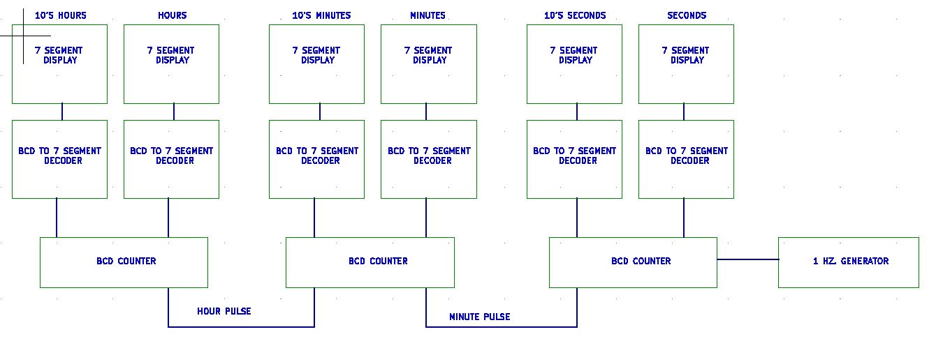
We decided on ONE board for this timer that will go inside the console itself. 

We also decided on smaller Seven Segment Displays (.54" vs the 1" we used on the clocks.)

There is no need for a controller, as all we will be doing is re-setting the timer to 00:00:00 and let it count.

For a reset, our console module will provide a "HIGH" when ever you push the Channel Button. (More on this later).

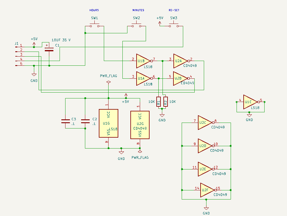
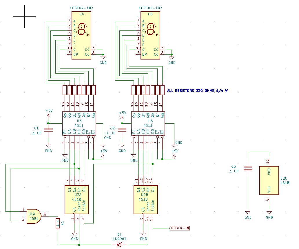
So here is the diagram for the Timer.


The timer works just like the clocks, only we use 3 of the 60 MODS

This will be a 60 hour counter. I can not imagine needing more. If you want a 100 hour counter, just leave off the 4081 section feeding the hours module. (U-5C)

The timer is re-set via a relay that closes when it receives a 'high' (1) from the console. The relay contact goes though 4 diodes that will feed a momentary +5 V to the re-set pins.

Easy Peazy. Bob's your uncle.

You build this the same way that you made the Clocks. Place the components, run the busses, and then wire it up.

Don't forget to TEST as you go along.

Everything 'should' work as designed. If so, let's go ahead and order the circuit board from JLC Pro.

Here is the blank board we got.

Let's stuff some parts, starting with the counter circuit and the seconds part of the timer. 

When that is verified as working, move onto the seconds section, then the minutes.

There you go, one timer ready to mount in the Mixer Panel.

We will now set this aside, and forge ahead.

-----------------------------------------------------------------------------------------------------------------------

Some final thoughts on the clock/timer.

It was hard to get it to come together, but well worth the effort. 

Yes, I could have used a PIC/PUC or whatever they are called. Or an Arduino. Or even a programmable chip.

But I love CMOS and I am an old fart.

I ran into on LARGE issues with the finished board. When I hit the "reset", all the digits returned to 'zero" EXCEPT for the 'minutes' digit. It would always land on "1".

So I went back to the bread board to see if I could figure it out. For some reason, adding a resistor to the output of the 4018 solved the issue. I also added a couple of diodes. (The schematics and pictures do MATCH the fixed version.


I tested a wide variety of circuits. 


And yes, I had a few failures and changes in the designs.


But now I have 2 digital clocks in my Ham Shack. (one set to GMT, the other set to LOCAL time)

And a timer for the console.

I learned and relearned a lot of things doing this phase.

But I am glad it's over.

I hope you got as much out of it as I.

So now we have our clocks and timer completed and "running like a clock', we will move on.

It's time to check the clock and timer off of our Planning List.

MIXER PLANNING

1) POWER SUPPLIES

+/- 15 VDC XMFR 1

+/- 7.5 V DC XMFR 1

+ 5.0 VDC (CLOCK/TIMERS) XMFR 2 OR COMMERICAL UNIT

SCHEMATICS

CIR BOARDS

CABINET


2) TIMER / CLOCK - SEPERATE UNITS FROM MIXER DUE TO SPACE LIMITS

12 HOUR MOD 60 MOD 60 MOD 12

24 HOUR MOD 60 MOD 60 MOD 23

TIMER UNIT

RE-SET PANEL

DISPLAY BOARD SCHEMATIC CIR BOARD

MAIN BOARD SCHEMATIC CIR BOARD

60 SEC/MIN MOD SCHEMATIC CIR BOARD

23 HOUR MOD SCHEMATIC CIR BOARD

12 HOUR MOD SCHEMATIC CIR BOARD

CABINET

PROTO TYPE

FINAL


3) HEADPHONE AMPLIFIER

DESIGN

SCHEMATIC

PROTO TYPE

CIRCUIT BOARD


4) CUE AMPLIFIER

CAN ALSO USE AS A TEST AMP WHILE BUILDING AUDIO BOARDS

DESIGN

SCHEMATICS

PROTO TYPE

CIRCUIT BOARDS


5) POWER AMPLIFIER (REPLACES TASCAM PA-30)

DESIGN

SCHEMATICS

PROTO TYPE

CIRCUIT BOARDS


6) OUTPUT BOARD

DESIGN

SCHEMATICS

PROTO TYPE

CIRCUIT BOARDS


7) MONITOR SELECT

DESIGN

AVOID OLD STYLE SWITCHES, USE DIGITAL

SCHEMATIC

PROTO TYPE

CIR. BOARD


8) PGM / AUD / MONO SELECT

DESIGN

AVOID OLD STYLE SWITCHES, USE DIGITAL

SCHEMATIC

PROTO TYPE

CIR. BOARD


9) INPUT SELECT

DESIGN

AVOID OLD STYLE SWITCHES, USE DIGITAL

SCHEMATIC

PROTO TYPE

CIR. BOARD


10) AUDIO INPUT BOARD

DESIGN

RS-12 VERSION

SCHEMATIC

PROTO TYPE - NOT DOING A PROTO TYPE

CIR. BOARD


11) MONITOR BOARD

DESIGN BASED ON MONITOR SELECT DESIGN

SCHEMATIC

PROTO TYPE

CIR. BOARD


12) EXTERNAL MONITOR BOARD

DESIGN

SCHEMATIC

PROTO TYPE

CIR BOARD


13) VU METER BOARD - SEPERATE UNIT ON SHELF

ONLY USED BECAUSE IT IS ALREADY BUILT

14) LED METERING - ON BOARD

USE RS-12 CIRCUIT REG LED'S OR BAR GRAPHS ????

SCHEMATICS

PROTO TYPE

CIRCUIT BOARD


15) D.A. AMPLIFIER

DESIGN

SCHEMATIC

PROTO TYPE

CIR BOARD


16) 4 PORT EXPANDER BOARD

DESIGN

SCHEMATIC

PROTO TYPE

CIR BOARD


17) POWER SUPPLY DISTRIBUTION BOARD ??

MAY BE NEEDED WITH MULTIPLE BOARDS ??


YEAH, Number 2 is completed !!!!!!


Coming up next on "Let's Build An Audio Console"-------- We were going to do an Audio Amplifier next, but changed our minds. 

I think we may move onto the audio INPUT cards and a way to feed 4 stereo inputs into ONE Input.

Hope you come along.


God Speed, Mother Nature.


.

.
.
.

The information presented here in this web site is for personal use only and may not be
 used commercially
We make no claim as to the accuracy of the information with-in. 


CHAPTER 9 - - - CLOCK ENCLOSURE

WELCOME BACK!!!!


    We are now ready to mount our Clocks in some type of enclosure. 

    I opted for a side-by-side configuration right above my computer monitor. I may mount the VU meters above the clocks, but that is a project for another day.

    Since we are not a wood working blog, and your needs will differ, I decided this chapter would be more pictures than design. I will give some helpful hints as we go along. 

    A lot of my woodwork designs are done during the construction rather than before.

    I know that is not the correct way, but it's my way.

    So here we go.

    I am going to start by mounting the two clocks on a large board, so I can get an idea of the cabinet size that will be needed.

    If I am clever, I can have a skeleton version mounted, then build the box to put it in.

    The first thing to do is figure a way to mount the DISPLAY boards. I opted to mount them right against the Plexiglass. If I can figure out the proper bracket, I can avoid putting bolts through the Plexi.

    I 'think' I have an idea.

    We also need to come up with a scheme to mount the controller board.

    I am going to try to 'hide' the re-set switches behind a magnetic panel that I can remove to set the clocks, then replace it. When I made the VU meter box for my old mixer, I hid all the adjustments behind a wood panel, that I could unscrew to gain access. It worked perfectly.

    Then we mount the Clock boards.

    We want to keep in mind that we may need to get at all of this for any needed repairs or modifications.

    The first thing we did was get a large piece of plywood to use as a temporary base. (We will make a nice one later)

    One the longest side of your board, measure in about an inch and cut a groove along that side. Make the groove wide enough so the RED Plexiglass can slide in.    

Here I have cut a groove in the temporary plywood base to slide in the plexiglass

    Now you should make a set of brackets to hold the display modules.

    I took some aluminum stock, cut it to 10". 

The BLACK mark is where I will bend the aluminum

    I then used my metal brake to bend them into a 90 degree "L" One side of the "L" is ___", the other side is ____". We will be mounting our displays on the short part of the bracket,

BEFORE THE BEND
AFTER THE BENDING PROCESS

    You can also use a hammer and a vice, but they will not come out right.

    You can see the brackets on the right are NOT square, while the ones on the left line up perfectly.  

-----------------------------------------------------------------------------------

    You can get a metal brake at Harbor Freight. This is the one that I use.

METAL BRAKE 

-----------------------------------------------------------------------------------

    You might also be able to find some readymade brackets that will suit your needs.

    The idea is to get the display right up against the red plexiglass.

    Now that we have our brackets made, let's mount up the two display boards.

    Take your time and get them LEVEL!!!

    Here is a shot of the brackets in use.

    We can now proceed to mount the little controller board. It goes underneath the display board. (In the center) Make sure the switches do NOT go beyond the front of the plexiglass.

When I started to look at mounting the controller, I realized that I did NOT leave any room on one side for the brackets. So, I had to re-make them.

Original controller   

 Take your plexiglass over to a bandsaw or scroll saw and cut out the area for the switch bank.   

    We will be placing a strip over the front of the switches to hide them. 

    Here is my initial idea.

    Yes, one of the plexiglass covers is not in the groove all the way. Remember, this is all 'temporary' to get some idea of the sizes and procedure we will use on the main cabinet.

    Now we can mount the two boards (temporarily)

I will have to shorten the Ribbon Cables on the Right-Side clock.

    At this point I wired it all up and verified that everything was still functioning as designed.

    I did make one more change in the design. Since these clocks are going above the computer monitor, I decided on a separate power supply. I still have the original 5 Volt supply from my last mixer project, so I mounted that in the clock box. You can see it in the picture above. It is right above the clock boards.

    I will use my console power supply to power the timer in the mixer.

    Now that we have some ideas, let's build the box.

    As some of you know, in 1990, my wife and I bought an old Victorian home in the Historic District. After three years of renovations, we moved in and lived there until I retired in 2017. And yes, we made a BOATLOAD.

    When we were renovating, I saved a lot of original Florida Heart Pine. I decided to use this 125-year-old wood for this clock cabinet.

    Here are the boards glued up and drying.

    When the glue is dry, I will cut to size and sand, sand, sand, and sand some more. This project calls for some real woodworking. I plan to finish the cabinet in a clear lacquer. The redness of the Pine will shine through.

    If you want more info on Heart Pine and how to buy it, there is a lumber mill just north of us that specializes in the recovery and milling of old logs. They were featured in an episode of Norm Abrams 'New Yankee Workshop.' Most of the wood for Norm's Heart Pine projects came from here.

GOODWIN HEART PINE

    It is by far my favorite wood. 

    Now that the glue has dried, we scrape off the excess with a scraper. Then I will cut it "almost to size" and start sanding.

    One I have sanded to my satisfaction, I will trim all the boards to size. 

---------------------------------------------------------------------------

And here we are a year or two later and we still have not finished up the cabinet. But don't worry, it's on the way.

---------------------------------------------------------------------------

Let's build up the easy one. A regular up counter.


 Now we can move on to  CHAPTER 10 - - -  BUILDING THE CONSOLE TIMER

God Speed, Mother Nature.

-
-
-
-
-

The information presented here in this web site is for personal use only and may not be
 used commercially

We make no claim as to the accuracy of the information with-in. 


Wednesday, June 1, 2022

CHAPTER 7 - - - BUILD THE CLOCK

WELCOME BACK !!!!

    Now that we have learned how the clock functions (and have looked at 5.325 million designs) let's see what we decided on.

    We used the 4510 chip in our final design for the 12 hour clock. It was the easiest route to take. But it was fun learning how to make a clock go from 12 to 1 using standard timer chips. It was much more complicated but it did work as designed.

    We were going to piggyback the 1 HZ module on the main board but decided against it. So we will build it directly onto the clock board. I will be using the 4060/4013 version.

    We are also going to use the SAME 1 HZ counter to supply the SAME count to the 24 hour clock as well. More on that later. 

    A word here about the 1 HZ circuit. I built a ton of them on the breadboard, and they ALL worked. (Some more accurate than others) But when I put them on a circuit board, they gave me FITS. It turned out that because of my poor soldering techniques, we were burning up the CRYSTALS.... So, I beg you-------- Heat sink the crystal when soldering. I have a little tool I use.

So here we go .......


1 HZ Generator - 4060 with 4013 version

Here is our final design for the 12-hour version.
The pull-down resistors may not be needed but I added them to help stabilize the AND gates.

And the Circuit Board

 Now let's build this on the bread board.
Wanna see it go from 12 o'clock to 1 o'clock?
Course you do.

    Now that we have the design and it seems to work on the Bread Board, let's build the Prototype.
    
    We built the Display Board earlier in our journey, so we will move directly to the main board.
    For the main board, I will be using one of the boards we bought from Amazon. 


(I cut it in HALF to get the board for the other clock.)
Using my schematic we start by placing our IC Sockets, Jacks, resistors, caps, and diodes.
Then we run our Power and Ground Bus, and wire power and ground to the IC's.

HELPFUL HINT - I label all the sockets with the name of the IC. It will help when I start doing the point to point wiring,

Ready to run the POWER AND GROUND BUSES
    Starting to run the buses

    As far as the point-to-point wiring goes, start with the 4511 outputs to the resistors then onto the jack that runs to the display board.
    
    (Don't forget to TEST as you go along.)

    Here is the proto type with all the 4511's wired to the resistors then to the output jacks that feeds the Display Board.
    After testing I use some finger nail polish to secure the small wires so they don't move and break a connection. If you don't like the 'look', you can use CLEAR polish.

    Let's wire up the outputs from the 4518's to the 4511's.

    Another way to secure your wires is with a piece of copper wire. I cut a 3 inch piece and make a "U". Then I insert it across the wire through two holes. I then turn the board over and twist the two ends together. I don't really care for this look, but I do use this method to hold wires tight against the board while the 'polish' dries. I then cut the copper wires and remove them, thus leaving the secured wire in place.

    BUT, don't make it too tight !!!!!!
--------------------------------------------------------------
    Now let's wire up the 4510's. 

    Once we complete that task, we can move on to the inputs to the 4510's and the 4518's.

    Start with the seconds module..

    Once the SECONDS Module is complete and working, move on to the minutes section. (Do not hook the seconds output to the minutes input YET)

    Now you can build out the MINUTES section of your clock.

    Get it working before moving on.

    Now that the SECONDS and MINUTES are working and counting, you can now run the leads from the SECONDS module to the MINUTES module.
    
    Does the Second output count the Minutes??? 
Yes, it does.

    Move onto the HOURS Module, and get it up and running. 
    
    Once done with the hours, you can connect it's input to the pulse coming out of the minutes module.

    Now add the set switch panel. (The next chapter will have more info on the Switch Controller design.)

   The clock controller we designed using the two HERTZ pulse to set the hours and minutes, never worked as planned. (it required several OR gates and got a bit complicated.) So we decided to use 5 volts thru a tactile switch. With a resistor and capacitor, it worked PERFECTLY.  I finally realized that I was making this clock more DIFFICULT than it needed to be.

    Here is the FINAL design for the switch panel. I wanted to use tactile switches. They seemed to work better than the toggles that I tried.


Could not be simpler.

    To set the clock, simply hit 'RESET' when your master clock seconds hit "00".... Then set the minutes, by pushing the 'SET MIN' switch enough times to advance to the current minute,

    Do the 'Hours' the same way.

    Congratulations, You just built a digital clock.

    The 24 hour version is made in the same manner. The biggest difference is the omission of the 2 x 4510 chips. 
    
    They are replaced by ONE 4518 chip.

    Here is your schematic for the 24 hour version.

AND THE BOARD TO GO WITH IT

Just follow the schematic and build it using the techniques described above.

Now let's talk about some of the custom modifications that I made since I'm running 2 clocks and one timer.

I used the same 1 HZ counter for BOTH clocks, in order to keep the 'seconds' count the same. I used jumpers so if one of the modules dies, I can still keep both clocks running. Since I built 1 HZ counters on both boards, I can use the unused counter to flash the LEDS between the segments. Or I can add another AND gate. That's what I decided upon.

Now that the clocks are done I am thinking about the timer. I don't think I'll be counting past 60 minutes, but what the hell. Let's build a six digit timer. You can easily leave off the hours section if you so desire.

BUT, let's not get ahead of ourselves.

Let's move onto the discussion about the controller, then we can build a cabinet for the clocks.

YOU CAN NOW PROCEED TO CHAPTER 8 - - - CONTROLLING THE CLOCK.

 God Speed, Mother Nature.


.

.
.
.

The information presented here in this web site is for personal use only and may not be
 used commercially
We make no claim as to the accuracy of the information with-in. 


Sunday, April 10, 2022

CHAPTER 8 - - - CONTROLLING THE CLOCK / TIMER

And welcome back,. We can now take a look at how to set and re-set the 6 digit clock.

Over the course of the last few months, I have been building (and modifying) a control panel.

I determined that it was BEST to have a controller for the CLOCK, and a different controller for the timer.

Here is the first version (CLOCK) that I tried.     


Here is a look at the control switches. Used for setting the minutes and hours. We can also reset all the digits to ZERO as well as putting the 'count' in a HOLD mode.

Let's look at the big picture.


The re-set is the easiest. The re-set switch sends 5 V to each reset pin. This pulse goes through 6 1n4148 signal diodes to protect each pin from any stray pulses.

Let's see how the minutes can be set. (The hours work the same way.)

A pulse from the 10's of seconds digit, sends a HIGH to an OR gate. When ever the OR Gate sees a HIGH on either PIN it will send a HIGH to the counter.

We are feeding a 2 hz. signal into the minutes set switch. When that switch is closed, the 2 HZ pulse is set to the other input of the OR gate. It will send a 2 HZ HIGH to the count pin. Simply open the switch when you get to the count you want.

Using momentary switches are a help in this application.

If you want to STOP the Clock, (HOLD the Count) simply close the HOLD Count switch.

When the HOLD Count switch is open the 1 HZ timing pulse routes through the switch and onto the Seconds counter. 

When closed the 1 HZ count pulse is replace by 5 V. Thus stopping the seconds digit from counting.

 Open the switch and the 5 V is replaced by the 2 HZ pulse, and counting continues.

-----------------------------------------------------------------------------------------------

There are a couple of issues with the above. 

First, it adds yet MORE I.C.'s to the project and second, why do we need a "re-set"? This is a clock not a timer. And it requires sending the seconds pulse through the switch panel. Let's try to make it SIMPLE.

We thought about taking an example from the schematic for the clock kit that we bought at the beginning of our journey. It's been running perfectly for six months. 


+5 volts enters the set switch (S-2) on the left.

When closed, the 5 volts goes to a 1n4148 diode then onto the enable pin of either the minutes or hours. A capacitor to ground helps to "de-bounce" the switch.


And it works !!!!!  The pull down resistors are not critical but they do provide some stability to the AND gates.

If you want to add more chips, you could use the 2 HZ pulse to set your clock. However, I found that to be overkill.

We did add a HOLD switch, just like on the clock kit that we built.

It simply sends 5 Volts to the 1 HZ IN pin. That will override the 1 HZ pulses and put the clock in the "HOLD" position.

To set your clock, simple put it in the HOLD position when your master clock hits :00.

Then set your minutes to the next minute, and the hours to the correct hour.. 

When your master clock hits that time, simple turn the HOLD to RUN.

Done.

BUT WAIT !!!!!!! This did not work as planned. Sometimes the clock would 'jump' when you set it to run. Debouncing the switch did not solve the issue, but it did help.

SO, let's think a bit.

Why 'pause' the clock waiting for the for the master clock (seconds" to catch up????

Let's just RESET the seconds to :00, then set the minutes and the hour???

In order to reset the seconds we need to remove the GND from PIN 7 of the 4518. I added a 10 K ohm pull down resistor to PIN 7 and GND.

Now I can re-set the clock seconds to :00 when the master clock reaches :00.

It worked like a charm.

Here is the final design:


As my old friend Lee Corso likes to say,
"Not So Fast"

I still had an issue with some switches not working as desired. So, I kept looking.

Here is what I found.

You can score these from DIGI-KEY.
The only issue is they switch a GROUND signal, and we need 5 Volts. SO, we insert a CD4049 Hex Inverter to change the GND pulse to a +5Volt pulse. And Bob's your uncle.


This one worked PERFECTLY.

One thing I have learned while on this journey:  Sometimes simple is BETTER....

Now let's start to consider the case/cabinet or other means of mounting the clock.

YOU MAY NOW MOVE ON TO CHAPTER 9 LET'S BUILD A CABINET
.
.
.
.

The information presented here in this web site is for personal use only and may not be
 used commercially
We make no claim as to the accuracy of the information with-in. 


.

CHAPTER 6 - - - The CLOCK !!!

Welcome back

 To understand how this magic all happens, let's take a look at a Block Diagram of a digital Clock.

Let's make it easier:
We already have our one second pulse, so now let's put it to work.

The 1 HZ pulse feeds a BCD Counter that will count 0-9. Then at "10", a pulse will feed the 10's of Seconds counter. Now your display reads 10. It will now count from 10-19. When the display goes from 19-20, a pulse will again trigger the 10's of seconds counter to increase to 2. Now the display reads 20. It will continue to count this way increasing the 10's of seconds digit, once every ten seconds. 

When it reaches "60", the 10's seconds counter will send a pulse to the next section. (It works exactly the same) in order to count the minutes. When the minute section hits 59:59, it will send the hours sections a pulse and re-set.

But wait !!! How do you get these counts to display properly ??

Now that the BCD timer knows what time it is, we need to convert that BCD code into something we can see !!

Anyone who watches The Big Bang Theory knows the world only sees ones and zeros. It is the building block of ANYTHING digital.

So, if it is JUST ones and zeros, it should be simple, right??

Yes, it is simple. IF you use the ones and zeros correctly. Remember, this clock will do whatever YOU tell it. If it doesn't work, you are telling it incorrectly.

Back to work.

The BCD timer chip exports the count as a four digit code.

Each number has a different code.

For example the "0" digit expresses itself as 
0 0 0 0.
The "1" digit is  0 0 0 1.

If you look at the third line, you will see the 0 0 0 0 signifying the digit 0.

Remember the A,B,C,&D lines are the 4 outputs of the BCD Counter chip. On some schematic draw programs the ABCD shows up as Q1,Q2,Q3, & Q4.

The BCD to 7 segment decoder will see the 0 0 0 0 and light up the digits for the number 0.
 So we are going to light up LED 'a,b,c,d,e, and f'. Leaving the 'G' turned OFF.

And when it moves to number 1 (0 0 0 1 in BCD language) it will light up segment b & c.

And that's how we get a count. (0-59)

Now lets take a look at the circuit.


Looks like the block diagram, doesn't it ???? The one second pulse enters the CD4518 on pin 10 and the chips starts counting the seconds . When it goes from 9 to 0, Pin 14 goes high, sending a pulse to pin # 2, causing the 10's to count up by one. Now it will count from 0-99.

But Hoss, we want it to count from 0-59.

OK, let's get it to re-set from :59 to :00.

If you look at the BCD chart, look at the code for "6"

 0 1 1 0

Yep, when the tens digit hits "6" we will see a 'High' on BCD lines "c" and "b".

In our chip that is pins 4 & 5. Using an 'and' gate we can insert those two "highs" and get a pulse at :60 to reset the Counter. (AND feed a pulse to the next section.

But doesn't line 'c' and 'b' also go high on the number 7??

Very true my friend, But the tens digit will never reach 7 since it will reset when it reaches 6. Brilliant, isn't it??

A quick word about AND gates.

One of the easiest multiple-input gates to understand is the AND gate, so-called because the output of this gate will be “high” (1) if and only if all inputs (first input and the second input and . . .) are “high” (1). If any input(s) is “low” (0), the output is guaranteed to be in a “low” state as well.

 The most common AND gates are the 2 input and 3 input. There are AND gates made with more than three inputs, but this is less common than the simple two-input variety. 

A two-input AND gate’s truth table looks like this:

So if you place a 'LOW' on any of the two inputs, you will see a 'LOW" at the output. BUT, if you place a "HIGH" on each input you will see a 'HIGH' on the output.

Remember we said that the number 6 gives you a 'HIGH' on two pins, we feed those 'HIGH's' to the AND gate. We only get a 'HIGH on the output when the digit reaches # 6. We use that "HIGH' to reset the timer to '0' And the process repeats itself.

Let's go ahead and bread board this circuit and play with it.

When you get this up and running, you can build a duplicate circuit as well... This will be for the minutes.

Now comes the hour. This one is a bit 'trickier' than the Seconds and minute because we want it to go from 12 to 1 NOT 12 to 00.

I found many circuits on line but they would only go from 12 to 0. That's fine for a 12 hour TIMER but not for a clock. Designing the 24 hour clock was easier.

Let's take a look at that schematic for the hours section.

As with the MOD 60 Counter, the input pulse (count) come into Pin 10 (4518), and the unit starts to count. When it reaches '0', PIN 14 goes High and sends a pulse to Pin 7 That causes the Tens of second digit to increase by 1 and the cycle continues. When the count reaches 24, the AND Gate goes into action. Pin 8 and 9 of the AND Gate goes High thus causing a High to appear at Pin 10. That pin sends a re-set pulse to Pins 7 and 15 causing the hours digits to RESET to '00' And the cycle starts over.

Now comes the hard part. Getting a 12 hour clock to work.

(Spoiler Alert) I will tell you at the end how to accomplish this the EASY way. But I wanted you to understand the circuit.

Since I could not find a circuit that worked, I studied up on how these chips function. As we learned earlier, each number has its own unique code 0,0,0,0 for the number zero. 0,0,0,1 for the number 1. 

Resetting our clock to :00 is easy, but we need to build on that and get that :00 to move to :01.

So let's get a 12 hour circuit that resets to :00


(Pull down resistors omitted for clarity.)

In order to reset from '12' to '00' we need to see a '1' in the tens place and '2' in the sec place.

Looking at our chart, we see that when it displays a '1' pin 6 on the tens unit goes high.

SO WE HAVE A '1'

Now we see that when a '13' is displayed PINS 11 & 12 goes HIGH.

WE NOW HAVE OUR '2'.

SO let's feed the 11 & 12 pins into an AND gate.


The output of that gate goes to an input on another gate.


The other input of that gate is connected to PIN 6 on the tens unit.

So when the unit displays a '3', we get a High on the output of the AND gate. Feeding that into another AND gate along with the HIGH from Pin 6, we get a HIGH on the output of the second AND gate. We can use that HIGH to reset BOTH counters to '00'.


So we reset the unit to '00', we can work with that.

We can feed  each digit into to 4 input AND GATE.


In order to go from '0' to '1' we need to see ZERO on both displays. Feed each of the 4 lines into a NAND gate (U-6A and U-6B) and we get 2 high's out.

 We then feed each of the HIGH's into another AND gate (U5D) to get a HIGH out.

Since we need a PULSE (rising and lowering) this HIGH will NOT work to count the hour digit.


BUT


If we take that HIGH and feed it to another AND gate (U-5B), we can just use the 1 or 2 HZ pulses to feed the other input of that AND gate. This will give us a PULSE that we can use.

That output will be sent to the count pin (Pin 10 of the 4518) We then go from 00 to 01.

But I don't want to see the zeroes.

You won't for very long because of the speed at which these chips work. The '00' shows up only long enough for the Gates to do their magic and increase the count. When that happens the '00' disappears. Using the One HZ counter on that AND Gate means the '00' may show up for ONE SECOND. If you use a TWO HZ pulse the '00' may show for as long a 1/2 sec.

But remember, this only happens 2 times a day for maybe a second or two. I think it's a fair trade off. Don't you?, Course you do.


Now the SURPRISE: Check out this diagram.

(This is not a complete diagram)

In this case the clock pulse comes in to pin 15, (not 10). and, this chip is DIFFERENT. The 4510 does the same job as the 4518 EXCEPT you can get it to always go to the number '1'. (Thus avoiding MORE IC's.)

I tried this one out, and it works !!!!!!!! So, we can use 2 of the 4510's in our hour circuit.


That's all the time we have for today. We now have a working schematic for a nice 24 or 12 hour clock.

But Hoss, how do we set the timer ????

We need a control panel. And we will get to that soon. 

Next time we will finish up the proto types and discuss building the clock and getting it running.

See you then.


YOU CAN NOW MOVE ONTO CHAPTER 7 - - - BUILD THE CLOCK


God Speed, Mother Nature.


.

.
.
.

The information presented here in this web site is for personal use only and may not be
 used commercially
We make no claim as to the accuracy of the information with-in. 


INPUT BOARD

And welcome back to our project. Now, we are starting on the INPUT BOARD. The RS Series Console used 6 Channel Input boards; we are going to...