Here we go again with another circuit addition to our Mixer/Console.
Buckle up dudes and dudetts, this may be a long one.
Since we MAY need more than 6 Inputs, we found a way to add more without taking up too much space.
We use an expander board.
This circuit will be wired up to feed up to 4 stereo feeds into ONE Input.
You can also use it in REVERSE to route up to 4 stereo feeds from any output.
I built two of these for the dreaded rat invested Console I built many years ago. (see CHAPER ONE )


I found the LATCHING switches on EBAY. I added some LEDs to show what switch was pushed in. To the left is the actual relay boards. (More on that to come)


They got the idea of scrapping the mechanical (wafer type) push switches.
The little expander boards worked well. Except for ONE issue. The switches would get dirty and make poor contact, causing the relays to drop out.
Here is where we depart from the OLD design and re-do a few things. Why you ask?
The switch problems were one of the few drawbacks to the older RS console design.
In the RS Console I installed at the radio station (1995) I continually had to replace switches. In all fairness, the problem was usually caused by heavy handed DJ's who never knew how to treat equipment properly.
This console was not designed to take a ton of abuse.
So, we are going to try to eliminate all the mechanical switches and use I.C.s instead.
Let's take a look at the schematic for the main expander board.

The 4 additional inputs come in via TB2 & TB3 and is routed to Relays K3, K4, K5, & K6. The output of those relays is then routed to relays K1 & K2. The proper relay configuration is selected via the switch panel J1. I will show that in a bit.
Here is how my new board will look like. 


-------------------------------------------------------------------------------------------------------------------------------------------------
OK, now onto the controller.
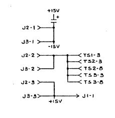
Here is how Radio Systems controlled their expander board.

You will also note that 'Select A' is not hooked up to anything. That is because "A" is the default selection. In other words, ALL the relays are 'relaxed' or non-energized.
The Radio Systems controller card was also used as a Timer Control. The only difference is what components are mounted with the switch. This way, they only had to keep ONE version in stock, then loaded the appropriate diodes or resistor.


You can see the additional 'holes' for components. I am showing my spare Timer Controller as I do not have a 4-port switch bank. But you get the idea, right?
Now, since we don't like the switches (and I haven't even mentioned how hard it is to get a square hole into a panel) we are going to REPLACE them with I.C.s. (we hope)
We did not show that the switches are fed with +15 V and the switches then send that +15V to the card.

Right?
Right?
So, let's start searching....................
OK, first up, I want to build a circuit that will light 4 LEDs in sequence then start over. That will give me the +5V to turn on a transistor. I really liked the 4017 CMOS chips we used when we were building the 1 sec. timer that drives clocks. So, let's search there.
I can also use this idea when it comes to building up the "Monitor and Headphone Control" cards."
I am back!!! I found 4 ideas I want to try.


And C. Let's not forget D.
C was the winner winner, circuit dinner. (Too much Diners Drive Inns & Dives,)
I played around with A, B, & D and never got them to work as advertised.
Let's take a look at the Breadboard.

Only issue is with this circuit you press the switch 5 times. On the 5th push it shows NO lights. Then you press again for #1.


We can now try it out !!!
Let's see if we can drive a transistor with this circuit.
First effort started out great then went to hell with exploding transistors and HOT I.C.s. Not a fault of the circuit, but the nut building it.....SO until Amazon comes with deliveries, we will work on something else.
Now that we have spare parts, let's try this again.
This is where we all hum the theme from "Jeopardy".
OK, now that we have all that crap a workin', let's do some switch work.
Even using a tackle switch, the circuit may not be stable due to switch bouncing. A capacitor helps but I think we might be better off going a different route.
On the RS console input boards, they used nice switches to drive a 4011 chip.
And I have a TON of their nice switches.


Let's take a look at how this idea will come together.
Here is what I came up with.

Now that we have 4 outputs, we need to get them to switch +15 Volts that will go to the Expander board to energize the proper relays.
I found that I could easily switch a ground pulse by using a 2N4401 Transistor. I need that ground pulse to fire off a PNP transistor that will switch the +15 Volts. The +15 Volts is then fed to the Expander board control inputs.
Let's look at the Counter.

Now see it work!! I know, we already did this once... But this is fun!!
Now, let's hook up some transzippers.


"Hey Mister Engineer, why are there only three outputs going to the expander card ?????"
Remember, count #1 means nothing. That is a default setting with all of the expander relays relaxed. So, no voltage is needed.
I did hook up one relay. (unseen) You can hear it 'click on and off' in the video.
OK, now for some "adjustments."
I decided to use the larger switches that I had from other RS Consoles. It is a lighted push button, and I can add a couple of connections and light it up. I did that with the small switch as well. It won't track the switching but will look cool.
We can also mount some separate LEDs to show where the count is.
Here is the revised schematic. You will notice some "Power Flags" on the drawing. They are only there to let KICAD understand what I am doing, so it does not "error". They are not part of the schematic in the real world.

It worked like a champ, so I then took the nice Radio Systems switch, (Dial Light) found a bulb and hooked it up. Here it is on the bread board.

It's not as bright as it looks. Now we can let this cook a while, so we can start on a circuit board for this part of the show.
And here is the board for the Controller.

And the 3-D view


Now that we have our design and the parts from Amazon, let's build up the prototype. And check our board design at the same time.
That's next time. See you then. I think it's time for a refreshing adult beverage.

You may now proceed past go, collect your $200.00 and land on the Next Chapter.
YOU CAN NOW MOVE ON TO CHAPTER 12 ---- BUILDING THE EXPANDER PROTO TYPE
God Speed Mother Nature.
Live Long and Prosper


No comments:
Post a Comment