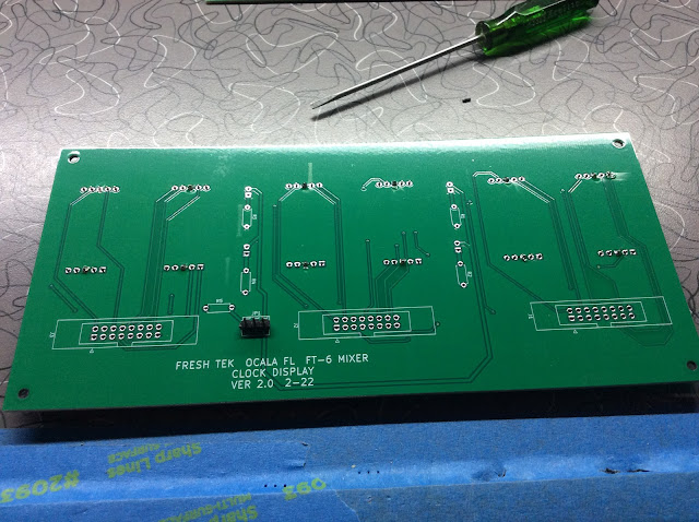
OK, friends. Since I was ordering boards for the Power Supplies, I went ahead and ordered boards for the Clock Display. That way I can proceed with the clock enclosure. I can replace the CLOCK BOARDS at a later date. But I want to get the displays mounted in the final position. SO, let's make it so....
First a look at the Schematic for the DISPLAY:
I made some changes in the final design. I eliminated the Molex connector for +5 V and GND, as well as the power LED. The GND is now obtained thru Pins 15 & 16 of J3. I also added separate feed for the Blinking LED's.
Here is the FINAL Display Schematic.
JP1 receives the 1 sec pulse for the semi-colons via J2 Pins 15 & 16. You can choose either the LED in between the digits OR you can use the Decimal point on the individual displays. It's your choice.
And the BOARD Views:
Now that the boards are here, let's stuff some components and check it out.
I place the pins on the display and insert it into the board. I tape it down, turn it over, and solder the pins place. I repeat this process for each segment. This keeps everything in proper alignment.
Repeat with the jumper and the IDC cable sockets.
And the resistors.
And the display board is complete.
Yes, I did realize that one of the displays was upside down!
Now I need to remake the switch panel with some JLCPCB boards.
I will wait for all the board BEFORE I build the cabinet.
I also decided to replace the factory made 5 V Power Supply. JLCPCB had a minimum of 5 boards, so I have some of the 5V boards left over.
So, the plan is to get a 12 or 24V DC power pack and feed that to the 5V supply.
And we need to get the 12- & 24-hour clock circuit boards made.
Since JLCPCB ships from China I am trying to do a multiple board order and save a bit on the shipping.
Coming up next, we are building an amplifier.
CHAPTER 14 - - - THE AMPLIFIER


No comments:
Post a Comment