Wednesday, January 11, 2023

CHAPTER 12 --- 4 PORT EXPANDER PROTOTYPE

 Having fun?? I hope so.

As always READ to the end BEFORE you start any construction.

Now it is time to fire up the solder melting machine and put together our prototype.

Before we fire up the soldering tools, let's get our parts together. And while we are doing that, we might just as well check out parts clearances for the board.

First thing to do is print out a copy of the board. (I set it to print just the Front Silkscreen and the Back Silk Screens.)

Now I cut it to size and place it on a piece of Styrofoam.

Now take a sharp instrument (I used an push pin) Gently stab each hole but just enough to put a small hole in the paper.

This will make sticking the parts on the fake board much easier.

Now we start placing our parts and checking the clearances. Here is what it looks like.

See why we do this? It looks to me like C-1 on the board is smaller than the .1 uf cap I am using.... SO back to Kicad to change the 'footprint'. And C-1 and R-1 are a bit too close to the chip, so I might just as well move them.

Moo-cho better. Now C-1 is the correct size and it and R-1 have moved up and to the right just a skuntch.

Now since this board will have components on the back, (Orange LEDs and all the connectors) I need to go with a double-sided board. 

I just happen to have one on hand, that I was going to use on another part of the project.

Let's go out to the shop and trim it to size and drill some mounting holes. (It's nice to have a full-blown shop)

And here we are with ALL of the components mounted to the prototype. 

Although I made the prototype a bit larger than the board, I think the RED LEDs are too close together. I may go back into the board and make that change. Remember, this will mount FACE UP onto the board panel. That's why all the connectors are on the BACK of the board. Aren't I the clever one???

And the back view.


The three orange LEDs are not really needed but do show the +15 Volts leaving the last transistor verifying that the entire circuit is working. I think I will leave them for now. The nuts and bolts are there as a 'temporary' standoff. Final length TBD.

And while we are playing around, let's check the footprints on the main board.


Note to self: "Self, you might want to check footprints BEFORE you spend three hours running traces on the board in KICAD. Oh well, let's correct it and LEARN from it." 
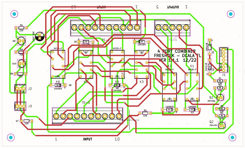
Here is a look at the newly revised boards.


 OK, here we are again. Let's print 'er and recheck the clearances. 

Then I took one of my larger boards out to the shop and cut it down to size.

I drilled some mounting holes in the board and mounted some stand offs. These stand offs help elevate the board when putting long leaded components into place.

Here is how it looks:


I did not have a 7-pin connector, so I used a six pin. (The 7-pin connector does not use all 7 connections, so it's not a big deal)

Note: I found a 7-pin connector later.

I also used some .1 headers as a transistor sockets The LEDs and the relays are soldered direct to the board.

The LEDs show power coming to the board. +15 V and -15V.

Now we get out our circuit board picture showing the trace layouts. 

Using the traces as a guide, we will wire up the prototype.

I started with the audio input and output wiring to and from the relay contacts. Then with an ohm meter, I traced each wire through the unenergized relays to the output.

Once that is confirmed as correct, we move on to the actual electronic part of the schematic.

You can check the relay functions by placing +15 V on the proper pins on J-1.

For the audio checks, you can hook up an audio amplifier to the output and try 4 different audio sources.

Now let's put together the controller.... (ACTUALLY, WE DID THE CONTROLLER FIRST)

I decided that mounting the LED's direct to the board would cause a problem when doing the final mounting. So, I used sockets and external LED's. 

That meant I could abandon the idea of connectors on the back of the board. So back to a single board we go.

I spent some time fixing some schematic errors. D-8 and the transistor footprints were backwards.

The Prototype:

The LAST and Final Board version. (Wanna bet?)

And the boards showing the traces.

And a FINAL look at the Breadboard before I break it down.

-----------------------------------------------------------------------------------------------

Now that the proto type is finished, let's CHANGE IT!!!!!

Let's CHANGE EVERYTHING!!!!!

OH BOY!!!

OK, I know I keep changing things, but as you go along you get new and better ideas. This is why we do mockups, and prototypes. And then we do it again.

And you get to benefit from those ideas and changes.

If you want to build this expander using two boards, you have enough info to do so.

B U T,

I decided to combine the two boards into ONE in order to make mounting easier. (And I have am still undecided on how to mount all of these boards we are building)

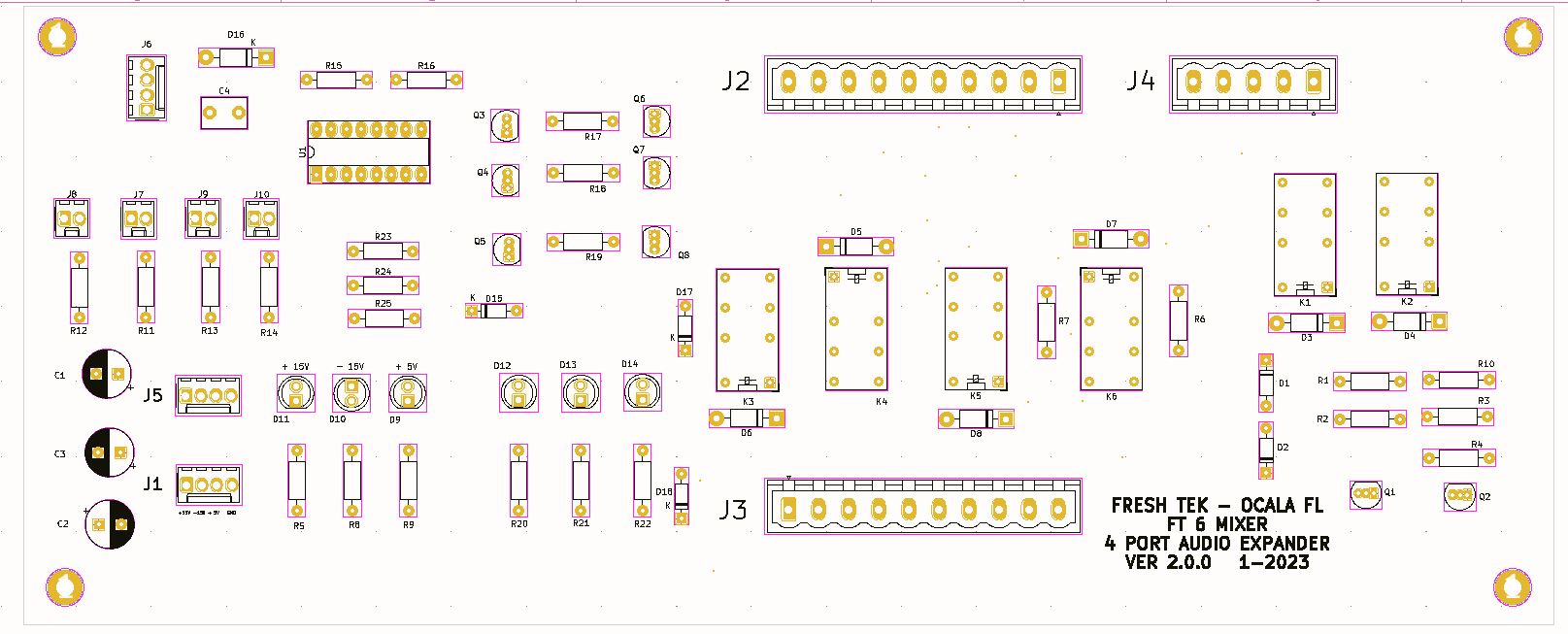
SO, here is the schematic:

And the Circuit Board:

And the 3D view

And the Footprints:

Step 1 :  CHECK THE FOOTPRINTS

Once you check the footprints, you can begin construction.

Building the prototype was easy. 

Start with mounting ALL the parts on to the board.


Having the parts on the 'footprint" checker made life easy. Just transfer them to the board and solder.

I did make my board a bit LONGER than the footprint version. No reason other than avoiding another cut on the band saw. The final version will be the correct length.

Wire the controller part FIRST. When that is built, TEST IT before moving on.


Here you can see the controller being tested. The RED LEDS are simply "Power ON" showing +5, +15 & -15V. The BLUE represents the three-transistor output feeding the relay circuit.

(Remember: When NO Blue lights are on, the relays are ALL DE-ENERGIZED)

And it worked PERFECTLY. 

On to the relay portion.

Once completed I realized that in Position #2 ALL the Blue lights came on. This is due to voltages feeding BACK to the LED's from D1 & D2. This does not cause any issues with the circuits function but may be confusing. So, I added three 1N4148 (D15, D17, & D18) diodes to eliminate the issue. 

I also noticed that if left with ANY of the relays energized, the unit would occasionally revert back to position #1. I solved that issue with a 10K pull down resistor from the CLK input of the 4017 to ground.

Here is the circuit working with all the relay drivers and relays connected.


Other issues:  The used Dial Co switches did NOT hold up. After some use the contacts started acting up. I thought it was switch bounce, so I added a .01 Cap from the CLK pin 14 of the 4017 to ground. That did not help, so I went back to the Switches I bought from ALL ELECTRONICS.

That means a new prototype switch panel with LED's.


And here it is in action:


I also discovered a problem with the way I mounted the transistors. I have been using a header as a socket, however one of the transistors was intermittent. I will solve that by soldering the transistors directly to the circuit board in the final version.

-----------------------------------------------------------------------------------------------

Now you can wire the relay audio wires. If you are proto typing, doing the audio wires LAST makes the earlier construction easier, as the audio wires do get in the way. Why do I always have to learn the HARD way?

Now you can test out your expander and mount it onto your mixer panel.

Or you can do what I did, ORDER some Boards from  JLCPCB.

I plan to make 2 of these for the Mixer.

But FIRST, let's show some FINAL pictures and schematic. We have made SO MANY changes during this journey, I wanted you to have the FINAL drawings.

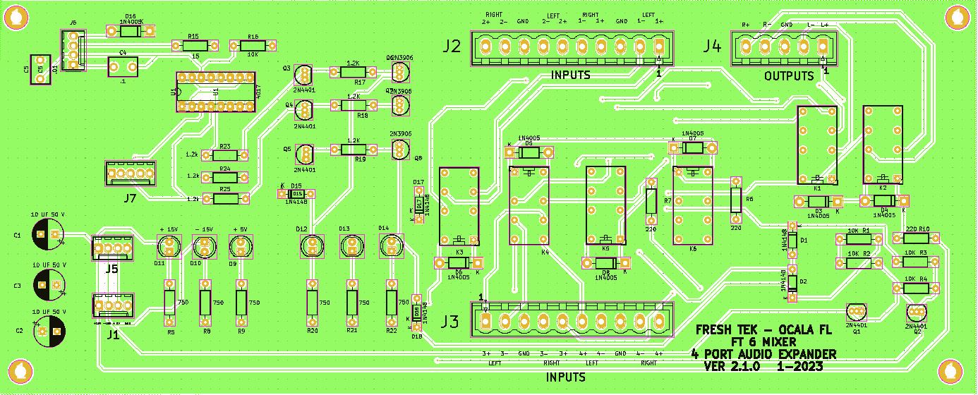


and the FINAL schematic.

I almost forgot!!!! You will need a switch panel. I made several and here is the FINAL version.

The big difference in this board is that the switch is mounted on the reverse side of the board.


Now we can order the boards and get the parts together.

Here are the boards from JLC PRO (Top & Bottom)


Let's start stuffing parts. Start with the power input then test. Move on to the 4017 stepper and test that. Then you should wire the transistors and make sure that part is working correctly. OK so far?? Wire up the Relays and finish it up.


And the finished product side by side with the prototype. (I used the transistors from the prototype.) 

A couple of notes here:

I used smaller footprints for the transistors. (MISTAKE) They were a royal PITA to solder. Next time I will use a larger footprint and .1 sockets.

I also had some issues with the input control. Moving a couple of wires around solved that issue.

I also discovered that the footprints for Q-1 & Q-2 were backwards... Reversing the transistors solved that issue. I will have to go into KICAD and fix that problem.

-----------------------------------------------------------------------------------------------

Final thoughts:

I wanted to attempt this board since I was researching how to eliminate the wafer switches. Those switches were also used on the Monitor/Headphone Select boards as well as the Input Select Board.

I found that different switches acted differently. I have a ton of used Dial Co switches from scrapped mixers, so I went through a few of those and chose the best one. But they acted up as well, so I chose a different type of switch. All was well. 

(Later Note:  I did have a ton of issues with switches not working properly. This was due to contact "bouncing." I tried a number of things that did not work well enough to be stable. I FINALLLY designed a circuit that worked!!! I used that idea on the 'Head Phone/ Monitor select board. 

I will ultimately redesign the 4 Port Control board as well.)

Designing something has been on top of my list for months, since I also can use what we learned here on the Monitor and Headphone Select circuits.

Let's take a look at our "TO DO" list and check off the 4 Port COMBINER!!!!!


MIXER PLANNING

1) POWER SUPPLIES

+/- 15 VDC XMFR 1

+/- 7.5 V DC XMFR 1

+ 5.0 VDC (CLOCK/TIMERS) XMFR 2 OR COMMERICAL UNIT

SCHEMATICS

CIR BOARDS

CABINET


2) TIMER / CLOCK - SEPERATE UNITS FROM MIXER DUE TO SPACE LIMITS

12 HOUR MOD 60 MOD 60 MOD 12

24 HOUR MOD 60 MOD 60 MOD 23

TIMER UNIT

RE-SET PANEL

DISPLAY BOARD SCHEMATIC CIR BOARD

MAIN BOARD SCHEMATIC CIR BOARD

60 SEC/MIN MOD SCHEMATIC CIR BOARD

23 HOUR MOD SCHEMATIC CIR BOARD

12 HOUR MOD SCHEMATIC CIR BOARD

CABINET

PROTO TYPE

FINAL


3) HEADPHONE AMPLIFIER

DESIGN

SCHEMATIC

PROTO TYPE

CIRCUIT BOARD


4) CUE AMPLIFIER

CAN ALSO USE AS A TEST AMP WHILE BUILDING AUDIO BOARDS

DESIGN

SCHEMATICS

PROTO TYPE

CIRCUIT BOARDS


5) POWER AMPLIFIER (REPLACES TASCAM PA-30)

DESIGN

SCHEMATICS

PROTO TYPE

CIRCUIT BOARDS


6) OUTPUT BOARD

DESIGN

SCHEMATICS

PROTO TYPE

CIRCUIT BOARDS


7) MONITOR SELECT

DESIGN

AVOID OLD STYLE SWITCHES, USE DIGITAL

SCHEMATIC

PROTO TYPE

CIR. BOARD


8) PGM / AUD / MONO SELECT

DESIGN

AVOID OLD STYLE SWITCHES, USE DIGITAL

SCHEMATIC

PROTO TYPE

CIR. BOARD


9) INPUT SELECT

DESIGN

AVOID OLD STYLE SWITCHES, USE DIGITAL

SCHEMATIC

PROTO TYPE

CIR. BOARD


10) AUDIO INPUT BOARD

DESIGN

RS-12 VERSION

SCHEMATIC

PROTO TYPE - NOT DOING A PROTO TYPE

CIR. BOARD


11) MONITOR BOARD

DESIGN BASED ON MONITOR SELECT DESIGN

SCHEMATIC

PROTO TYPE

CIR. BOARD


12) EXTERNAL MONITOR BOARD

DESIGN

SCHEMATIC

PROTO TYPE

CIR BOARD


13) VU METER BOARD - SEPERATE UNIT ON SHELF

ONLY USED BECAUSE IT IS ALREADY BUILT

14) LED METERING - ON BOARD

USE RS-12 CIRCUIT REG LED'S OR BAR GRAPHS ????

SCHEMATICS

PROTO TYPE

CIRCUIT BOARD


15) D.A. AMPLIFIER

DESIGN

SCHEMATIC

PROTO TYPE

CIR BOARD


16) 4 PORT EXPANDER BOARD

DESIGN

SCHEMATIC

PROTO TYPE

CIR BOARD


17) POWER SUPPLY DISTRIBUTION BOARD ??

MAY BE NEEDED WITH MULTIPLE BOARDS ??


---------------------------------------------------------------------------------------------------------------------------

Now we can move onto the next part of our project !!! CHAPTER 13 - - - CLOCK/TIMER - - THE FINAL BUILD OUT  See you then.


God Speed, Mother Nature.

.
.
.
.

The information presented here in this web site is for personal use only and may not be
 used commercially
We make no claim as to the accuracy of the information with-in. 


Saturday, January 7, 2023

CHAPTER 13 - - - CLOCK/TIMER - - THE FINAL BUILD OUT

OK, friends. Since I was ordering boards for the Power Supplies, I went ahead and ordered boards for the Clock Display. That way I can proceed with the clock enclosure. I can replace the CLOCK BOARDS at a later date. But I want to get the displays mounted in the final position. SO, let's make it so....

First a look at the Schematic for the DISPLAY:

I made some changes in the final design. I eliminated the Molex connector for +5 V and GND, as well as the power LED. The GND is now obtained thru Pins 15 & 16 of J3. I also added separate feed for the Blinking LED's. 

Here is the FINAL Display Schematic.


JP1 receives the 1 sec pulse for the semi-colons via J2 Pins 15 & 16. You can choose either the LED in between the digits OR you can use the Decimal point on the individual displays. It's your choice.


And the BOARD Views: 


Now that the boards are here, let's stuff some components and check it out.


I utilize 40-pin sockets for the displays and the LED seconds displays. Simply cut off the desired number of pins.


I place the pins on the display and insert it into the board. I tape it down, turn it over, and solder the pins place. I repeat this process for each segment. This keeps everything in proper alignment.


Repeat with the jumper and the IDC cable sockets.


And the resistors.

And the display board is complete.

Yes, I did realize that one of the displays was upside down!

Now that the display is complete, we will proceed to the clock. We will use our bench power supply to run the clock until we create the power supply and cabinet.

Now I need to remake the switch panel with some JLCPCB boards.

I will wait for all the board BEFORE I build the cabinet.

I also decided to replace the factory made 5 V Power Supply. JLCPCB had a minimum of 5 boards, so I have some of the 5V boards left over.

So, the plan is to get a 12 or 24V DC power pack and feed that to the 5V supply.

And we need to get the 12- & 24-hour clock circuit boards made.

Since JLCPCB ships from China I am trying to do a multiple board order and save a bit on the shipping.


Coming up next, we are building an amplifier.

CHAPTER 14 - - - THE AMPLIFIER

.
.
.
.
.

The information presented here in this web site is for personal use only and may not be
 used commercially
We make no claim as to the accuracy of the information with-in. 


Tuesday, December 27, 2022

CHAPTER 11 - - - 4 PORT EXPANDER CARD AND CONTROLLER

 Here we go again with another circuit addition to our Mixer/Console.

Buckle up dudes and dudetts, this may be a long one.

Since we MAY need more than 6 Inputs, we found a way to add more without taking up too much space.

We use an expander board.

This circuit will be wired up to feed up to 4 stereo feeds into ONE Input.

You can also use it in REVERSE to route up to 4 stereo feeds from any output. 

I built two of these for the dreaded rat invested Console I built many years ago. (see CHAPER ONE )


The 'toggle' switches on the top of the module were used to SET the timer/clock.

I found the LATCHING switches on EBAY.  I added some LEDs to show what switch was pushed in. To the left is the actual relay boards. (More on that to come)

Useless fact:  The original mixer concept called for "modules" rather than a large top that opened up. This idea was scrubbed when the folks at Radio Systems sent me a complete top. They had a program where a customer could have their top replaced by a newer and more modern top. And they took pity on this old dude and sent me one of the older "trade ins."

In other words, your older style RS Series Console

would turn into a nicer looking more modern "Millennium" console.

They got the idea of scrapping the mechanical (wafer type) push switches.

OK, enough B.S. Let's get back to why we are here.

I did build two of these units for the original mixer, but I think only one will be needed here. JLCPCB has a 5-board minimum, so I will have extra boards. Might as well make two.

If you look closely at the main board, you will see that J-1 & J-2 are wired in parallel. The extra connector would power a 2nd expander if you needed it.

The little expander boards worked well. Except for ONE issue. The switches would get dirty and make poor contact, causing the relays to drop out.

Here is where we depart from the OLD design and re-do a few things. Why you ask?

The switch problems were one of the few drawbacks to the older RS console design.

In the RS Console I installed at the radio station (1995) I continually had to replace switches. In all fairness, the problem was usually caused by heavy handed DJ's who never knew how to treat equipment properly.

This console was not designed to take a ton of abuse.

So, we are going to try to eliminate all the mechanical switches and use I.C.s instead.

Let's take a look at the schematic for the main expander board.


The 4 additional inputs come in via TB2 & TB3 and is routed to Relays K3, K4, K5, & K6. The output of those relays is then routed to relays K1 & K2. The proper relay configuration is selected via the switch panel J1. I will show that in a bit.

Here is how my new board will look like.

Component placement
Bottom Copper layer
Top Copper layer
-------------------------------------------------------------------------------------------------------------------------------------------------

OK, now onto the controller.

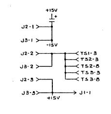
Here is how Radio Systems controlled their expander board.

Note: R4 is a ZERO-ohm resistor. It is used as a "jumper" on their switch bank controller. J1-1 goes to +15 V.

You will also note that 'Select A' is not hooked up to anything. That is because "A" is the default selection. In other words, ALL the relays are 'relaxed' or non-energized.

The Radio Systems controller card was also used as a Timer Control. The only difference is what components are mounted with the switch. This way, they only had to keep ONE version in stock, then loaded the appropriate diodes or resistor.


You can see the additional 'holes' for components. I am showing my spare Timer Controller as I do not have a 4-port switch bank. But you get the idea, right?

Now, since we don't like the switches (and I haven't even mentioned how hard it is to get a square hole into a panel) we are going to REPLACE them with I.C.s. (we hope)

We did not show that the switches are fed with +15 V and the switches then send that +15V to the card. 

So....If we develop a 4-digit counter, then feed the +5v (High) to a transistor, we can turn on the transistor and feed +15 V to the card.

Right? 

Right?

So, let's start searching....................

OK, first up, I want to build a circuit that will light 4 LEDs in sequence then start over. That will give me the +5V to turn on a transistor. I really liked the 4017 CMOS chips we used when we were building the 1 sec. timer that drives clocks. So, let's search there.

I can also use this idea when it comes to building up the "Monitor and Headphone Control" cards."

I am back!!! I found 4 ideas I want to try.


Let's go to the breadboard and build up diagram A.  OK, Now for B.

And C.   Let's not forget D.

C was the winner winner, circuit dinner. (Too much Diners Drive Inns & Dives,)

I played around with A, B, & D and never got them to work as advertised.

Let's take a look at the Breadboard.

And we can watch it work !!!!

Only issue is with this circuit you press the switch 5 times. On the 5th push it shows NO lights. Then you press again for #1.

The circuit I found needed a slight revision. The original builder may have needed a "blank" setting, but I do not. 

Let's try THIS version on the breadboard.

I think we may have it.... No not really. Please follow to the end.

We can now try it out !!!

Let's see if we can drive a transistor with this circuit.

First effort started out great then went to hell with exploding transistors and HOT I.C.s. Not a fault of the circuit, but the nut building it.....SO until Amazon comes with deliveries, we will work on something else.

Now that we have spare parts, let's try this again.

This is where we all hum the theme from "Jeopardy".

OK, now that we have all that crap a workin', let's do some switch work.

Even using a tackle switch, the circuit may not be stable due to switch bouncing. A capacitor helps but I think we might be better off going a different route.

On the RS console input boards, they used nice switches to drive a 4011 chip.

And I have a TON of their nice switches.

I know what I said about square switches and mounting. But these have a little 'rims' around them that makes the mounting task a bit easier. The downside to these is they use incandescent bulbs that run on 15 volts. If I can't use the +15V from the transistor, I think I can just add another transistor. They did offer some LED "replacements" but they were not bright enough to suit me, and also worked on +15 V. We shall see how this develops as we go along.

Well, the Radio Systems nice switches did work well. I like the larger size.

BUT,

I went through some other switches and found this one from ALL ELECTRONICS (Part # MPB-35, and they are 3 for .99.) They also have a nice LED inside that I can light up... I scored a bunch of them.
I tried one of these hooked to the 4017 counter and it worked FLAWLESSLY. I bet I ran through 100 cycles, and it never bounced once. 

You can choose your own type of switch depending on your design.

So, let's continue with the controller.

 Let's take a look at how this idea will come together.

Here is what I came up with.


Let's go through the diagram. The 4017 chip is a basic counter chip that you may remember from our clock circuits. I want to send a +5 V pulse to Pin 14. That pulse comes from an outboard switch that goes to J-1. The counter will count 1 step with each push of the button. When you step from #4 the counter re-sets to # 1. LED D1-4 shows where the count is. 

Now that we have 4 outputs, we need to get them to switch +15 Volts that will go to the Expander board to energize the proper relays.

I found that I could easily switch a ground pulse by using a 2N4401 Transistor. I need that ground pulse to fire off a PNP transistor that will switch the +15 Volts. The +15 Volts is then fed to the Expander board control inputs.

Let's look at the Counter.

This shows the count on # 4. I used one of my smaller switches (see above) for the breadboard version.

Now see it work!! I know, we already did this once... But this is fun!!

Now, let's hook up some transzippers.

The green LEDs show 15 Volts leaving the output trans. I used those so we could see it in action. They are not really needed in the final design.

One the far right is a 2n4401 transistor. When it turns on, it turns on the transistor immediately to its left (2n3904) by giving it a ground. That transistor feeds the +15 volts to the connector. That voltage then goes to the expander board.

Let's walk through how it magic happens.


The output from the 4017 goes through R6 and enters the 2n4404 Base. (Q1) That turns "on" the transistor, and the ground flows through the collector and out of the emitter.

The output of the 2n4401 goes through R9 and into the 2n3906 at the base. (Q-4) The collector is wired to the +15 volts. When the transistor turns on, the 15 volts exits the emitter and on to the expander board.

"Hey Mister Engineer, why are there only three outputs going to the expander card ?????"

 Remember, count #1 means nothing. That is a default setting with all of the expander relays relaxed. So, no voltage is needed.

I did hook up one relay. (unseen) You can hear it 'click on and off' in the video.


OK, now for some "adjustments."

I decided to use the larger switches that I had from other RS Consoles. It is a lighted push button, and I can add a couple of connections and light it up. I did that with the small switch as well. It won't track the switching but will look cool.

We can also mount some separate LEDs to show where the count is.

Here is the revised schematic. You will notice some "Power Flags" on the drawing. They are only there to let KICAD understand what I am doing, so it does not "error". They are not part of the schematic in the real world.

It worked like a champ, so I then took the nice Radio Systems switch, (Dial Light) found a bulb and hooked it up. Here it is on the bread board. 


It's not as bright as it looks. Now we can let this cook a while, so we can start on a circuit board for this part of the show.

And here is the board for the Controller.

And the 3-D view


I made a couple more changes in the board design, by flipping some LED's and connectors to the reverse side. You will see why when we mount it all up. Trust me.

Now that we have our design and the parts from Amazon, let's build up the prototype. And check our board design at the same time.

That's next time. See you then. I think it's time for a refreshing adult beverage.

You may now proceed past go, collect your $200.00 and land on the Next Chapter.

  YOU CAN NOW MOVE ON TO CHAPTER 12 ---- BUILDING THE EXPANDER PROTO TYPE

God Speed Mother Nature.

Live Long and Prosper

.
.
.
.
.
.

The information presented here in this web site is for personal use only and may not be
 used commercially
We make no claim as to the accuracy of the information with-in. 


INPUT BOARD

And welcome back to our project. Now, we are starting on the INPUT BOARD. The RS Series Console used 6 Channel Input boards; we are going to...