Sunday, April 10, 2022

CHAPTER 8 - - - CONTROLLING THE CLOCK / TIMER

And welcome back,. We can now take a look at how to set and re-set the 6 digit clock.

Over the course of the last few months, I have been building (and modifying) a control panel.

I determined that it was BEST to have a controller for the CLOCK, and a different controller for the timer.

Here is the first version (CLOCK) that I tried.     


Here is a look at the control switches. Used for setting the minutes and hours. We can also reset all the digits to ZERO as well as putting the 'count' in a HOLD mode.

Let's look at the big picture.


The re-set is the easiest. The re-set switch sends 5 V to each reset pin. This pulse goes through 6 1n4148 signal diodes to protect each pin from any stray pulses.

Let's see how the minutes can be set. (The hours work the same way.)

A pulse from the 10's of seconds digit, sends a HIGH to an OR gate. When ever the OR Gate sees a HIGH on either PIN it will send a HIGH to the counter.

We are feeding a 2 hz. signal into the minutes set switch. When that switch is closed, the 2 HZ pulse is set to the other input of the OR gate. It will send a 2 HZ HIGH to the count pin. Simply open the switch when you get to the count you want.

Using momentary switches are a help in this application.

If you want to STOP the Clock, (HOLD the Count) simply close the HOLD Count switch.

When the HOLD Count switch is open the 1 HZ timing pulse routes through the switch and onto the Seconds counter. 

When closed the 1 HZ count pulse is replace by 5 V. Thus stopping the seconds digit from counting.

 Open the switch and the 5 V is replaced by the 2 HZ pulse, and counting continues.

-----------------------------------------------------------------------------------------------

There are a couple of issues with the above. 

First, it adds yet MORE I.C.'s to the project and second, why do we need a "re-set"? This is a clock not a timer. And it requires sending the seconds pulse through the switch panel. Let's try to make it SIMPLE.

We thought about taking an example from the schematic for the clock kit that we bought at the beginning of our journey. It's been running perfectly for six months. 


+5 volts enters the set switch (S-2) on the left.

When closed, the 5 volts goes to a 1n4148 diode then onto the enable pin of either the minutes or hours. A capacitor to ground helps to "de-bounce" the switch.


And it works !!!!!  The pull down resistors are not critical but they do provide some stability to the AND gates.

If you want to add more chips, you could use the 2 HZ pulse to set your clock. However, I found that to be overkill.

We did add a HOLD switch, just like on the clock kit that we built.

It simply sends 5 Volts to the 1 HZ IN pin. That will override the 1 HZ pulses and put the clock in the "HOLD" position.

To set your clock, simple put it in the HOLD position when your master clock hits :00.

Then set your minutes to the next minute, and the hours to the correct hour.. 

When your master clock hits that time, simple turn the HOLD to RUN.

Done.

BUT WAIT !!!!!!! This did not work as planned. Sometimes the clock would 'jump' when you set it to run. Debouncing the switch did not solve the issue, but it did help.

SO, let's think a bit.

Why 'pause' the clock waiting for the for the master clock (seconds" to catch up????

Let's just RESET the seconds to :00, then set the minutes and the hour???

In order to reset the seconds we need to remove the GND from PIN 7 of the 4518. I added a 10 K ohm pull down resistor to PIN 7 and GND.

Now I can re-set the clock seconds to :00 when the master clock reaches :00.

It worked like a charm.

Here is the final design:


One thing I have learned while on this journey ::  Sometimes simple is BETTER....

Now let's start to consider the case/cabinet or other means of mounting the clock.

YOU MAY NOW MOVE ON TO CHAPTER 9 LET'S BUILD A CABINET
.
.
.
.

The information presented here in this web site is for personal use only and may not be
 used commercially
We make no claim as to the accuracy of the information with-in. 


.

CHAPTER 6 - - - The CLOCK !!!

Welcome back

 To understand how this magic all happens, let's take a look at a Block Diagram of a digital Clock.

Let's make it easier:
We already have our one second pulse, so now let's put it to work.

The 1 HZ pulse feeds a BCD Counter that will count 0-9. Then at "10", a pulse will feed the 10's of Seconds counter. Now your display reads 10. It will now count from 10-19. When the display goes from 19-20, a pulse will again trigger the 10's of seconds counter to increase to 2. Now the display reads 20. It will continue to count this way increasing the 10's of seconds digit, once every ten seconds. 

When it reaches "60", the 10's seconds counter will send a pulse to the next section. (It works exactly the same) in order to count the minutes. When the minute section hits 59:59, it will send the hours sections a pulse and re-set.

But wait !!! How do you get these counts to display properly ??

Now that the BCD timer knows what time it is, we need to convert that BCD code into something we can see !!

Anyone who watches The Big Bang Theory knows the world only sees ones and zeros. It is the building block of ANYTHING digital.

So, if it is JUST ones and zeros, it should be simple, right??

Yes, it is simple. IF you use the ones and zeros correctly. Remember, this clock will do whatever YOU tell it. If it doesn't work, you are telling it incorrectly.

Back to work.

The BCD timer chip exports the count as a four digit code.

Each number has a different code.

For example the "0" digit expresses itself as 
0 0 0 0.
The "1" digit is  0 0 0 1.

If you look at the third line, you will see the 0 0 0 0 signifying the digit 0.

Remember the A,B,C,&D lines are the 4 outputs of the BCD Counter chip. On some schematic draw programs the ABCD shows up as Q1,Q2,Q3, & Q4.

The BCD to 7 segment decoder will see the 0 0 0 0 and light up the digits for the number 0.
 So we are going to light up LED 'a,b,c,d,e, and f'. Leaving the 'G' turned OFF.

And when it moves to number 1 (0 0 0 1 in BCD language) it will light up segment b & c.

And that's how we get a count. (0-59)

Now lets take a look at the circuit.


Looks like the block diagram, doesn't it ???? The one second pulse enters the CD4518 on pin 10 and the chips starts counting the seconds . When it goes from 9 to 0, Pin 14 goes high, sending a pulse to pin # 2, causing the 10's to count up by one. Now it will count from 0-99.

But Hoss, we want it to count from 0-59.

OK, let's get it to re-set from :59 to :00.

If you look at the BCD chart, look at the code for "6"

 0 1 1 0

Yep, when the tens digit hits "6" we will see a 'High' on BCD lines "c" and "b".

In our chip that is pins 4 & 5. Using an 'and' gate we can insert those two "highs" and get a pulse at :60 to reset the Counter. (AND feed a pulse to the next section.

But doesn't line 'c' and 'b' also go high on the number 7??

Very true my friend, But the tens digit will never reach 7 since it will reset when it reaches 6. Brilliant, isn't it??

A quick word about AND gates.

One of the easiest multiple-input gates to understand is the AND gate, so-called because the output of this gate will be “high” (1) if and only if all inputs (first input and the second input and . . .) are “high” (1). If any input(s) is “low” (0), the output is guaranteed to be in a “low” state as well.

 The most common AND gates are the 2 input and 3 input. There are AND gates made with more than three inputs, but this is less common than the simple two-input variety. 

A two-input AND gate’s truth table looks like this:

So if you place a 'LOW' on any of the two inputs, you will see a 'LOW" at the output. BUT, if you place a "HIGH" on each input you will see a 'HIGH' on the output.

Remember we said that the number 6 gives you a 'HIGH' on two pins, we feed those 'HIGH's' to the AND gate. We only get a 'HIGH on the output when the digit reaches # 6. We use that "HIGH' to reset the timer to '0' And the process repeats itself.

Let's go ahead and bread board this circuit and play with it.

When you get this up and running, you can build a duplicate circuit as well... This will be for the minutes.

Now comes the hour. This one is a bit 'trickier' than the Seconds and minute because we want it to go from 12 to 1 NOT 12 to 00.

I found many circuits on line but they would only go from 12 to 0. That's fine for a 12 hour TIMER but not for a clock. Designing the 24 hour clock was easier.

Let's take a look at that schematic for the hours section.

As with the MOD 60 Counter, the input pulse (count) come into Pin 10 (4518), and the unit starts to count. When it reaches '0', PIN 14 goes High and sends a pulse to Pin 7 That causes the Tens of second digit to increase by 1 and the cycle continues. When the count reaches 24, the AND Gate goes into action. Pin 8 and 9 of the AND Gate goes High thus causing a High to appear at Pin 10. That pin sends a re-set pulse to Pins 7 and 15 causing the hours digits to RESET to '00' And the cycle starts over.

Now comes the hard part. Getting a 12 hour clock to work.

(Spoiler Alert) I will tell you at the end how to accomplish this the EASY way. But I wanted you to understand the circuit.

Since I could not find a circuit that worked, I studied up on how these chips function. As we learned earlier, each number has its own unique code 0,0,0,0 for the number zero. 0,0,0,1 for the number 1. 

Resetting our clock to :00 is easy, but we need to build on that and get that :00 to move to :01.

So let's get a 12 hour circuit that resets to :00


(Pull down resistors omitted for clarity.)

In order to reset from '12' to '00' we need to see a '1' in the tens place and '2' in the sec place.

Looking at our chart, we see that when it displays a '1' pin 6 on the tens unit goes high.

SO WE HAVE A '1'

Now we see that when a '13' is displayed PINS 11 & 12 goes HIGH.

WE NOW HAVE OUR '2'.

SO let's feed the 11 & 12 pins into an AND gate.


The output of that gate goes to an input on another gate.


The other input of that gate is connected to PIN 6 on the tens unit.

So when the unit displays a '3', we get a High on the output of the AND gate. Feeding that into another AND gate along with the HIGH from Pin 6, we get a HIGH on the output of the second AND gate. We can use that HIGH to reset BOTH counters to '00'.


So we reset the unit to '00', we can work with that.

We can feed  each digit into to 4 input AND GATE.


In order to go from '0' to '1' we need to see ZERO on both displays. Feed each of the 4 lines into a NAND gate (U-6A and U-6B) and we get 2 high's out.

 We then feed each of the HIGH's into another AND gate (U5D) to get a HIGH out.

Since we need a PULSE (rising and lowering) this HIGH will NOT work to count the hour digit.


BUT


If we take that HIGH and feed it to another AND gate (U-5B), we can just use the 1 or 2 HZ pulses to feed the other input of that AND gate. This will give us a PULSE that we can use.

That output will be sent to the count pin (Pin 10 of the 4518) We then go from 00 to 01.

But I don't want to see the zeroes.

You won't for very long because of the speed at which these chips work. The '00' shows up only long enough for the Gates to do their magic and increase the count. When that happens the '00' disappears. Using the One HZ counter on that AND Gate means the '00' may show up for ONE SECOND. If you use a TWO HZ pulse the '00' may show for as long a 1/2 sec.

But remember, this only happens 2 times a day for maybe a second or two. I think it's a fair trade off. Don't you?, Course you do.


Now the SURPRISE: Check out this diagram.

(This is not a complete diagram)

In this case the clock pulse comes in to pin 15, (not 10). and, this chip is DIFFERENT. The 4510 does the same job as the 4518 EXCEPT you can get it to always go to the number '1'. (Thus avoiding MORE IC's.)

I tried this one out, and it works !!!!!!!! So, we can use 2 of the 4510's in our hour circuit.


That's all the time we have for today. We now have a working schematic for a nice 24 or 12 hour clock.

But Hoss, how do we set the timer ????

We need a control panel. And we will get to that soon. 

Next time we will finish up the proto types and discuss building the clock and getting it running.

See you then.


YOU CAN NOW MOVE ONTO CHAPTER 7 - - - BUILD THE CLOCK


God Speed, Mother Nature.


.

.
.
.

The information presented here in this web site is for personal use only and may not be
 used commercially
We make no claim as to the accuracy of the information with-in. 


CHAPTER 5 - - - CLOCK TIMER PT 2 -- 1HZ COUNTER AND DISPLAY BOARD

 AND WELCOME BACK !!!!

    Before we continue with BCD Decoders, 7 Segment Displays, and all that stuff, let's take a moment and revisit the 1 Hz counter part of the project.

    I tested 5 versions of the 1 HZ Counter.

    And I finally settled on the winner !!!!!


    This version uses less parts and a readily available crystal. The Green LED on the right shows us two pulses per second. The Green LED on the left shows the 1 Second Pulse.

    These LED's are not critical to the circuit other than verifying that it is working correctly.

    And here is a short video showing the proto type in action.


HELPFUL HINT:     I have a hell of a time keeping track of IC pins when I turn the board over. So I have started to MARK the underside of the board with a magic marker. You can mark Pin 1, or do what I so. I mark the + and GND Pin. 


    Sorry for the crappy picture, but you should be able to make out the RED circle indicating the Power IN (PIN 16) of the I.C. The black marks did not show up well.

    And the schematic :

   
 The other circuits I tested worked well. I especially like the MM6359 circuit. But you have to get the chip from CHINA. (Although you CAN get them) I liked the 4060 version as well.

Here is a board idea.


And here is a parts list for this 1 HZ COUNTER circuit:

C1-C2      22 PF CAPACITOR

C3            100 UF 25 V CAPACITOR

C4-5         .1 UF CAPACITOR

D-1-3        5MM LED  

J1              2 PIN MOLEX CONNECTOR  

J2              3 PIN MOLEX CONNECTOR  

R1            100 K RESISTOR 1/4 WATT

R2            10 MEG RESISTOR 1/4 WATT   

R3-5        330 OHM RESISTOR 1/4 WATT

U1            CD4060 CHIP AND SOCKET

U-2           CD4013 CHIP AND SOCKET

Y1            CRYSTAL

----------------------------------------------------------------------------

    Now on to the CLOCK !!!!    

    I decided on a SEPERATE Display Board for my clock. This is totally due to space issues and how my Radio Room is set up.

    Your needs may vary.

    So I am starting with display board, so I can get the enclosure put together and in place.

    (I ultimately went with a display board and clock board in the same cabinet. I also deleted J-1 and used spare pins on J-2 & J3) 

    Here is a pic of the Display Board and the main clock board during the start of prototype construction.

(I had issues deciding on connectors. I am currently waiting on some new ones to try.)


    The Display Board is almost done. Once the new connectors arrive I can remove the ones shown.

    Here is the schematic for the Display Board.


And here is a parts list for this DISPLAY circuit:


J1-J3        16 PIN HEADER 

J-4            3 PIN MOLEX CONNECTOR

JP1           3 PIN JUMPER

D1-D5       5mm LED (USE 4 RED AND GREEN)

R1-R6       330 OHM 1/4 WATT RESISTOR

U1-U6     Common Cathode Displays (size to suit)

And a look at the (almost) completed Proto Type


I changed the connectors, and added a jumper. This jumper selects either the LED's or the decimal point to blink on the seconds count. You get to decide what works for you. 


Once all the wires were in place and checked, I used some finger nail polish to hold them in place.

And the circuit board (back and front)


The "white" lines show the grounding points. This will fill in when I do the final board version.

I placed the connectors, jumper, jacks, and resistors on the back of the board. 

Now I can mount the unit on the workbench shelf and move on to the main board.
----------------------------------------------------------------------------------------------
Since I do not know how accurate my 1 HZ timer will be, I decided to "piggy back" the 1 HZ board on top of the main board. 


This way I can replace the whole circuit at one time. I may try the 4060 board first, then try the MM5369 circuit. Then we can keep the most accurate circuit. 

(NOTE: I eventually scrapped the separate board idea.)

Now I need to build a MOD60  sec. & min. module. I have the test module up and running. (MOD is for "module) and the 60 means it will count 00-60  (actually 0-59 then re set to 0)


The green board is my spare 1 second generator. (MM5369 chip) It feeds the 60 sec counter. This is the circuit I will be using for the Seconds and Minutes portion of the clock timer.

That's enough for today, next time we will explain how all this comes together to form our digital clock/timer.

See you then !!! 


God speed, Mother Nature

.
.
.
.
.
The information presented here in this web site is for personal use only and may not be
 used commercially
We make no claim as to the accuracy of the information with-in. 


CHAPTER 4 - - - CLOCK TIMER PART 1 - HOW TO GET A PULSE EVERY SECOND

 The rock band Chicago once asked. 'Does Anybody Really Know What Time It Is?'

With that in mind, I think we will need some sort of clock, or timer.

It can be internal to the mixer or external. It's your choice.

I am still thinking about that. (I am leaning towards an external timer/clock since I have space issues)

I have also decided to use CMOS chips. Old technology for sure, but I am an old dude. So no PICS, PUCS or any other thing you have to program.

I realize that these days there are tons of simple circuits for clocks out in cyber space. But what would we learn building those ??   

-----------------------------------------------------------------------------------------------

I have made several clock/timers over the years.  

Years ago, I had a need to provide a PULSE every hour at exactly :05 past each hour. It was to signal a computer that the hourly network news had finished, and it was now time for the next event. It used a CMOS digital timer and worked well for several years. Then the radio station was sold and we all moved on with our lives. (and careers)

-----------------------------------------------------------------------------------------------

When I built my first LARGE mixer, (the dreaded rat invested disaster in my garage) I built two clock timers. They went on each end of the console.

 However, they were built on perf boards. They worked but looked like something out of Junior High Shop class.


Another option would be to buy a kit. But it does defeat the purpose of designing and building your own.

But wait. I have an idea !!! Let's get one of those clock kits anyway. We can practice our soldering skills and end up with clock we can put in the Ham Radio Room. And at a price of  $15.99, you can't go wrong.

CLOCK KIT ON AMAZON


Let's put this thing together. It will give us a working model to refer back to.

HELPFUL HINT : I used headers as a 'socket' for the displays and the LED's. (We may need to rob a part or two later.)

OK, it went together with only a couple of SNAFU's. I lost a 10 MEG ohm 1/4 watt resistor. (damn those things are tiny !!!)

So I used a 1/2 watt unit that I had.

Upon powering it up, I found two issues. One was a segment on the minutes display that did not light. I traced that down to a missing trace on the board. Easy to jumper.

The other issue was one BAD display. It had 2 dead segments (In all fairness, I probably screwed the display up myself) Luckily, I had an ARDUINO kit that had a direct replacement.

It all worked like a champ !!!!

The displays look better than the lighting allows. 


I deem the clock kit a success. I'll stick it on the shelf and  leave it run. Let's see how it holds up. Then I can think about a case of some sort.

(Update:  It runs like a top. One issue I have is re-setting the 'seconds' to zero. You have to power it off, then back on at :00.)

Let's check the accuracy. We will check every morning at 0800 or there bouts.

FRIDAY                    8:44:30       CLOCK READS  8:44:30
SATURDAY              9:29:00       CLOCK READS  9:29:00      
SUNDAY                  7:39:00       CLOCK READS   7:39:01  
MONDAY               10:00:00       CLOCK READS 10:00:02       
TUESDAY                9:00:00       CLOCK READS   9:00:02 
WEDNESDAY        10:00:00       CLOCK READS 10:00:04 
THURSDAY           10:00:00       CLOCK READS 10:00:04
FRIDAY                    8:55:00       CLOCK READS  8:55:02

So, in a seven day period my AMAZON clock kit gained TWO seconds. Not bad results. I think it is a success.

Since this is a 24 hour clock, it will not roll over to :01. It will reset to 00:00:00 at midnight.

So I think I will use this clock in my ham shack and do a 12 hour clock for the mixer project.

Since we have this part done, let's do something I learned when I started to cook after retirement. CLEAN UP AS YOU GO ALONG.

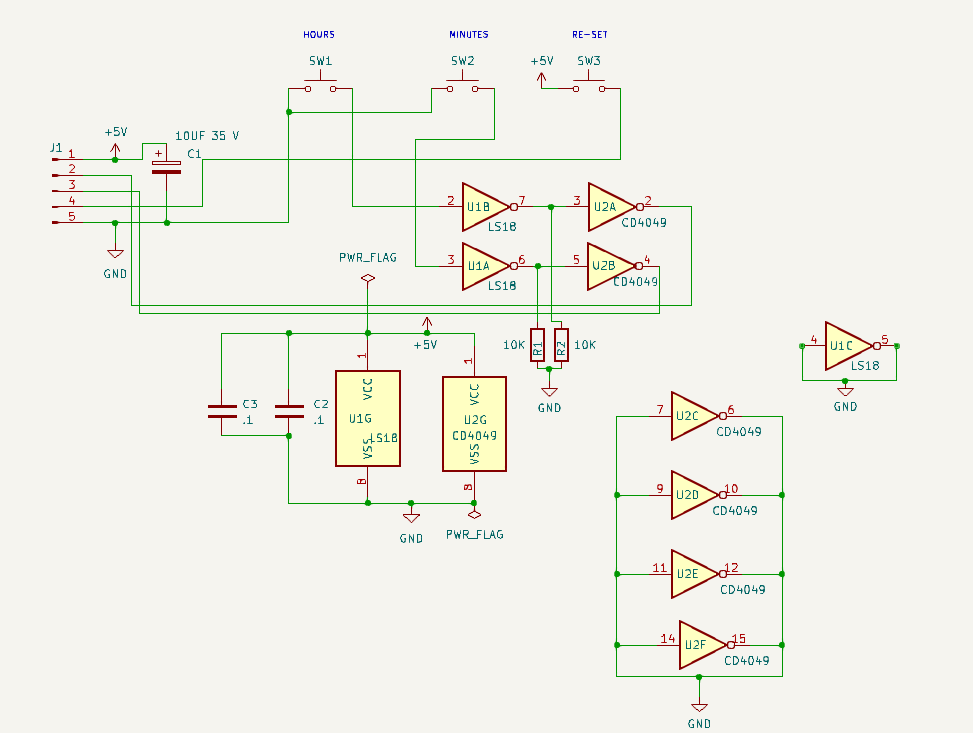
Now that we have learned soldering and have a working clock, let's start designing and playing with chips and resistors.

We can decide on a 12 or 24 hour clock later. I decided that it has to be one or the other. A 'switchable' 12/24 clock gets too complicated and time consuming for a project like this. I may re-visit the idea down the road.

-----------------------------------------------------------------------------------------------

What is the heart of any clock or timer ?????

It's the pulse you get every second. It must be consistent AND accurate.

I have three ways to get this pulse.

1) The 555 timer : Easiest to build BUT least desirable. Great for a timer, but may not be accurate over the long haul.

2)  The MM5369 chip : Good and accurate. This is what I used back in the 1990's. Bad news is they are discontinued. Good news is they ARE available on EBAY from China. Don't believe what you hear on the TV news. I received my chips direct from China in about 10 days.

3) The CD4060 chip. Easy to build and ACCURATE. This 14 stage Ripple Counter is the route I am thinking about taking. But before we do that, let's build the other two as well. Then you can choose your best option.

You can also get a 60 HZ pulse from the power line, but that technology is too old and not accurate enough to even attempt. If you are interested in this method, there are plenty of diagrams available online.

But here is a quick look at a circuit that "may" work."


While researching my next project, (A LARGE clock with NO IC's - Only transistors) I came across this 60 HZ second circuit.

I have NOT tested this circuit and won't until I start that project.
-----------------------------------------------------------------------------------------------

The 555 Timer.  

Here is our working schematic for a 1 HZ counter. Pin THREE is the output, driving an LED (so you can see that it is working.) Let's breadboard this puppy.


So, it does work as advertised. There are 21 million circuits out on the web for the 555 timer. (Al Roker counted them all) It's a great chip (for some things) but will not be accurate enough for us.

-----------------------------------------------------------------------------------------------

MM5369

Now, lets look at the MM5369.

My circuit using the MM5369 came from the book by Delton T. Horn. The book disappeared years ago, but I was able to find a replacement on Amazon.

50 CMOS IC PROJECTS

DANGER WILL ROBINSON --- There are numerous errors on some of the schematics. Proceed with CAUTION !!..

This is a circuit that I used many times building up timers for the Radio Station. It works well and is accurate. The 'heart' of the circuit is the crystal. A 3.58 MHZ crystal. It is easy to obtain, as this crystal was used in the 'color burst' section of older color TV's.


Let's Breadboard this circuit. I placed the LED's so we could "see" it work. In the real world, they are not needed. But I like flashing little lights, so I added them.

If you need more accuracy, you can replace C-1 with a variable cap. I did not get than anal.

Here is what a circuit board would look like.

I also found this circuit in a 1994 issue of Popular Electronics

You can download this issue and a TON of other old issues at :

DOWNLOAD POPULAR ELECTRONICS

There is also an interesting article on how to set up your shop. (Aimed more towards the 'kit' builder, this article does have a lot of good info.)

Be prepared to spend a ton of time on this site. And if you are a fan of Broadcasting History, grab an adult beverage and set aside HOURS of time. You can thank me later

So here is their circuit.

(I have added the LED's and resistor's)

SO back to the bread board we go.

Here is our bread boarded version of the POP COM 1 HZ counter for our clock/timer using an MM5369 chip.

The LED on the left shows the 60 HZ signal leaving the 5369 chip. The LED on the right shows a 1 HZ pulse.


CD4060
 
 
Another way to get your 1 HZ pulse is by using a quartz watch crystal and a 4060 IC. As with the MM5369, there are different versions of this on line. I plan to play with these circuits, then decide what circuit we will use. 

And back to the bread board we go...
 
This one turned out perfect. The Red LED on the left pulses 2 times per second the Green LED is the 1 HZ output. 

Here is a board to go with the circuit above.


Now let's put together a parts list.

If you want to make the 555 version

U-1         555 TIMER
RV-1       100 K OHM TRIM POT
C-2         .1 UF MYLAR CAP
C-4         10 UF 25 V ELECT CAP
R-3         1 K OHM 1/4 WATT RESISTOR
D-2         LED
R-4         1 K OHM 1/4 WATT RESISTOR      

-----------------------------------------------------------------------------------------------
FOR THE MM5369 VERSION (POP COM VERSION)

U-2        CRYSTAL 3.579545 KHZ
R-1        9.1 MEG OHM 1/4 WATT RESISTOR
C-1        33 PF CAP
C-3        33 PF CAP
U-2        MM5369 TIMER CHIP
R-2        510 OHM 1/4 WATT RESISTOR
D-1        LED
U-4        4548 COUNTER
U-3        4081 AND GATE

-----------------------------------------------------------------------------------------------
FOR THE MM5369 VERSION (MY VERSION)

C-1        47 PF CAP
C-2        10 PF CAP
J-1         4 PIN MALE MOLEX CONNECTOR   
R-1        1 K RESISTOR
R-2        10 MEG RESISTOR
R-3        10 MEG RESISTOR
R-4        330 OHM RESISTOR
4-5         330 OHM RESISTOR   
Y-1         CRYSTAL 3.579545 KHZ 
U-1        MM5369 I.C.
U-2        CD4017 I.C.
U-3        CD-4017 I.C.
D-1        LED
D-2        LED
-----------------------------------------------------------------------------------------------
CD4060 VERSION 

U-5    4060 BINARY COUNTER CHIP  
U-6    4017 COUNTER CHIP
Y-2    32768 KHZ CRYSTAL
R-9    10 MEG OHM 1/4 WATT RESISTOR
R-6    470 K OHM 1/4 WATT RESISTOR
D-5    LED
D-3    LED
R8     470 OHM 1/4 WATT RESISTOR
R-5    470 OHM 1/4 WATT RESISTOR
-----------------------------------------------------------------------------------------------
We will leave it right here for now. Let's let these circuits "cook" for a while. We want to make sure that the "magic smoke" does not escape from the components.

We do not have to decide on what circuit to use YET. I plan to leave them run for while, then we can decide. 

I will use one of the proto types to provide a pulse for the next part of the clock project.

Havin' fun yet ???

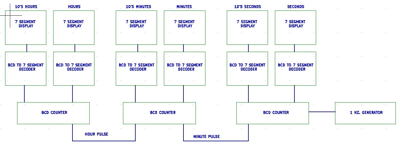
Next we will finish up our conversation on the 1 HZ timer board and talk some about how to display our time. Then we can get into the nitty gritty of the clock itself.


That's next time. Hope you come back !!!


God Speed, Mother Nature

.
.
.
.
.
The information presented here in this web site is for personal use only and may not be
 used commercially
We make no claim as to the accuracy of the information with-in. 


ANALOG VU METER BOARD

Let's talk about the Analog VU Meter Bridge. I decided to make the Meter Bridge separate from the mixer, because of limited space inside...